Microchip SAM E70 X PLAINED ULTRA开发板快速上手——GPIO、UART
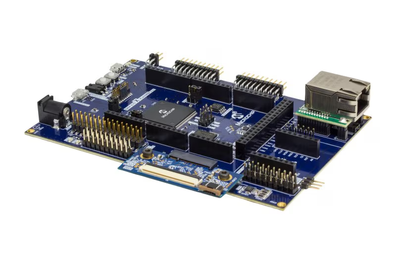
由于项目需要开始接触Microchip(原Atmel)家的这款MCU,使用工具是SAM E70 X PLAINED ULTRA开发板。本系列用于记录从0开始一步步熟悉这款MCU的开发过程。开发板外设资源丰富,之前一直是使用HAL库开发ST/GD系列的MCU,Microchip的开发风格与前两者存在一定差异,借此机会巩固一下基础知识。
- ATSAME70Q21B Microcontroller
- Cortex-M7 Core-based Microcontroller
- Max Speed: 300MHz
- Flash: 2048KB
环境搭建
安装IDE
Microchip官方IDE:MPLAB X IDE
Microchip支持图形化界面用来初始化外设,工具为MPLAB Code Configurator,6.x的版本自带MCC,在IDE Tools->Embedded下可以打开,同时可以通过Tools->Plugins下安装其他插件。
安装工具链
下载安装MPLAB XC32 C/C++编译器:XC32
创建工程
- File->New Project->Microchip Embedded->Application Project(s)。(不同版本IDE可能有所差异)
- Family->Device->Tool。(Tool中可以选择模拟器或实际的开发板)
- 选择工具链XC32
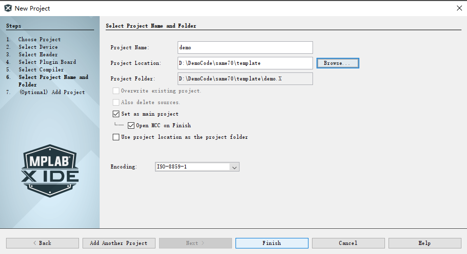
- 设置工程名称及保存位置,推荐勾选Open MCC on Finish,可以启动MCC完成初始化工作(这个工具加载特别慢)。
系统时钟概览
与大部分高性能MCU类似,系统使用RC/外部晶振通过锁相环完成倍频。
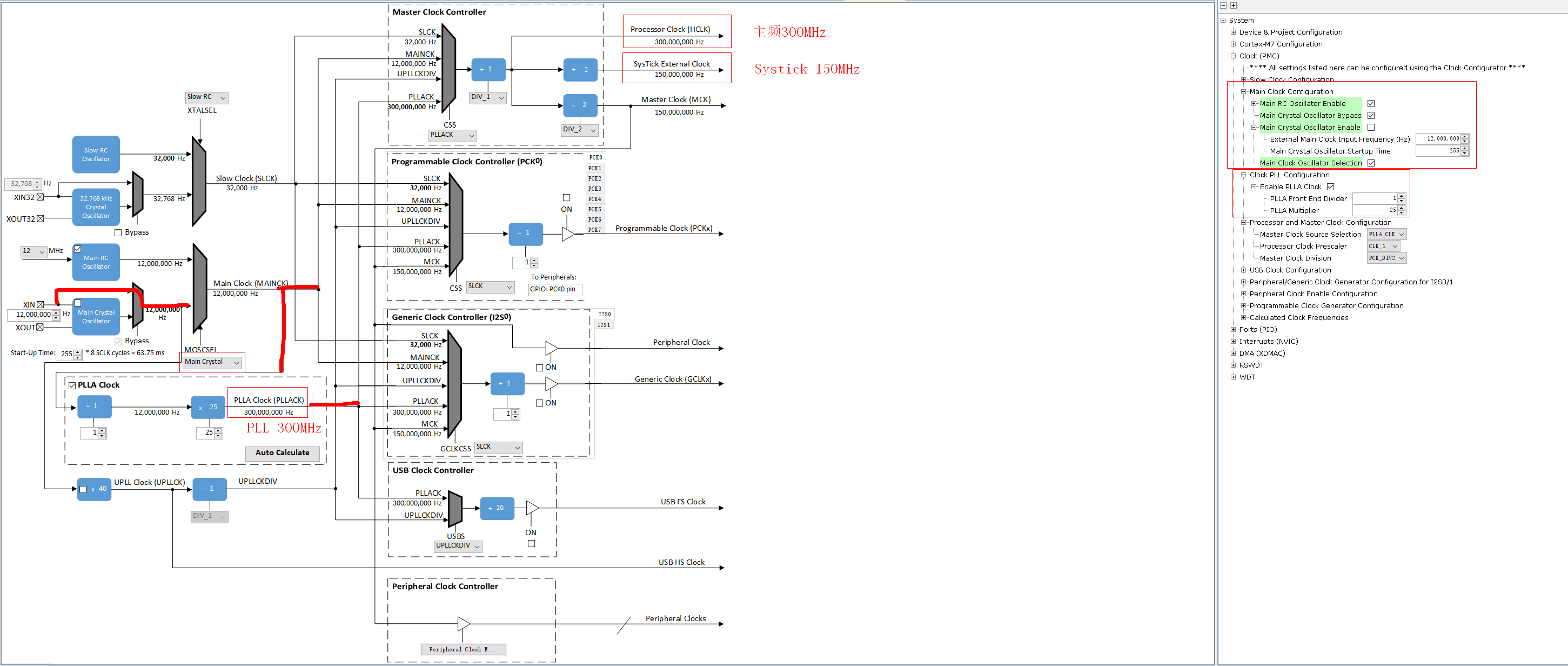
使用外部12MHz晶振作为时钟源,经过25倍倍频得到300MHzPLL时钟。
点亮第一盏流水灯
使用图形化配置界面,这里由于已经导入了开发板定义所以可以直接使能,界面如下:

如果是自己设计的板子,可以打开pin configuration界面进行设置。
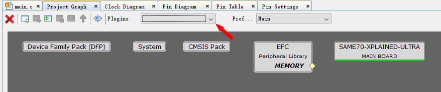
分别有三个界面,Pin Diagram类似与STM32CubeMX,但是对于这种引脚丰富的芯片不太友好,需要一个个点开查看引脚功能。
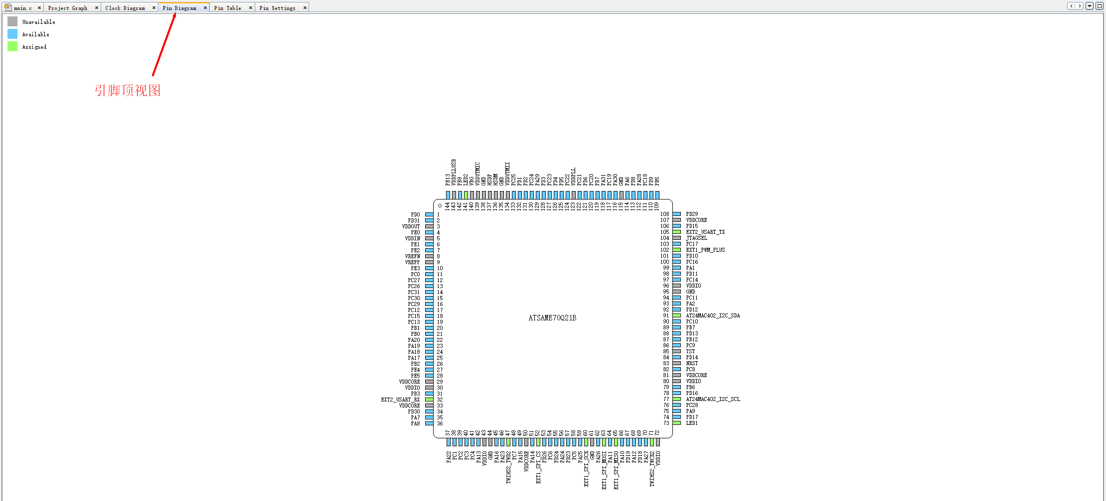
其次是Pin Table,可以直观看出每个外设有哪些引脚支持,比较友好。
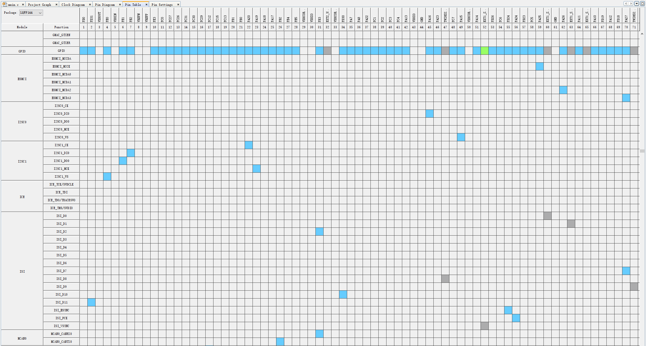
灰色代表不可用,蓝色代表可用,绿色代表已使用。
最后一种是列表的详细模式
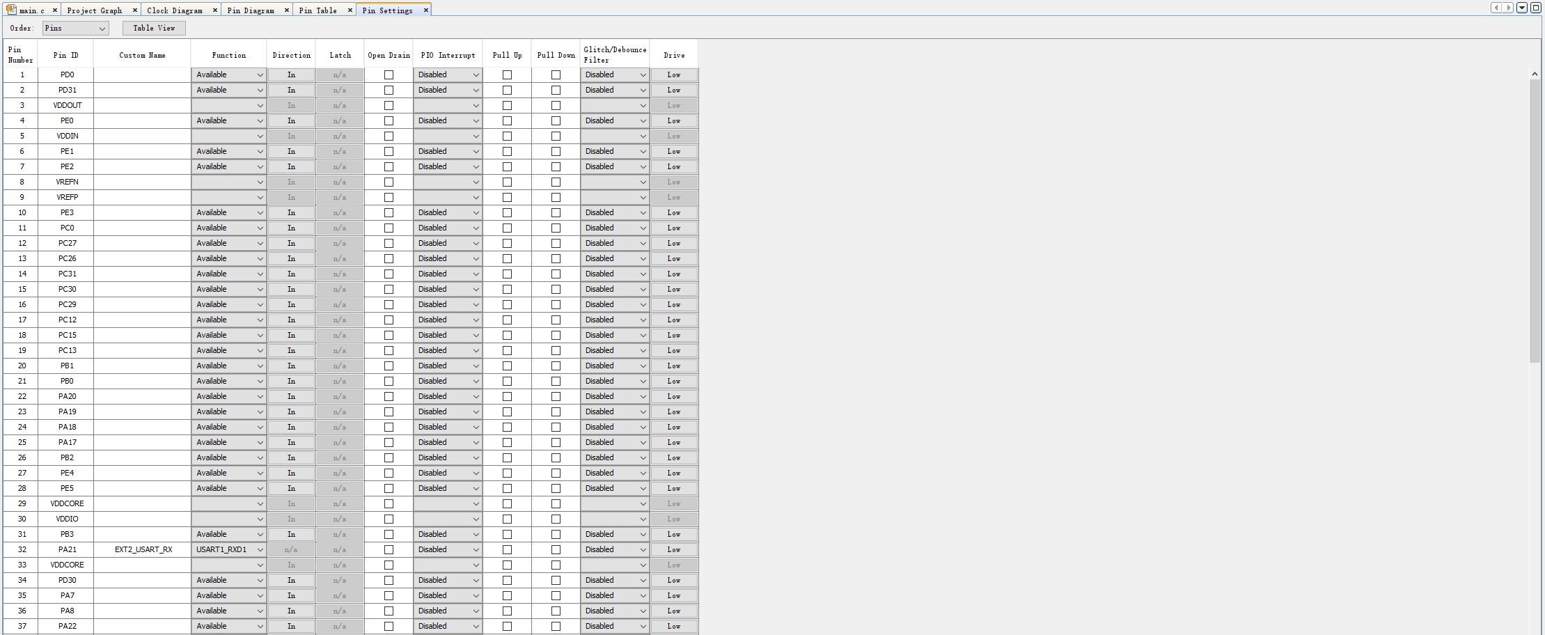
综合下来还是第二种较为好用,可以结合第三种一起使用。
我们现在已经使能了LED,点击左侧Generate就会自动生成代码。
Microchip以PLIB_xx命名外设库,GPIO对应的为plib_pio.c/plib_pio.h,包含对GPIO的初始化,读写、配置等函数。此外,因为我们设置了LED1、LED2引脚,会在plib.h中额外生成宏定义方便使用,此时如果我们想要点亮LED,可以进行以下操作:
从原理图我们可以看出,只需要给PA05一个低电平LED3就会点亮。
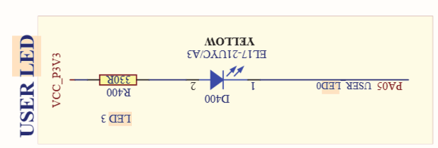
在main函数中添加以下代码:
int main ( void )
{
    /* Initialize all modules */
    SYS_Initialize ( NULL );

    LED3_Clear();

    while ( true )
    {
        /* Maintain state machines of all polled MPLAB Harmony modules. */
        SYS_Tasks ( );
    }

    /* Execution should not come here during normal operation */

    return ( EXIT_FAILURE );
}
LED3成功被点亮。
如果还想进一步使LED闪烁就是要用到延时函数,在前面我们已经使能了systick并设置周期为1ms,在plib_systick.c文件中有对应的延时函数SYSTICK_DelayMs。但是在使用之前,需要先调用SYSTICK_TimerStart或SYSTICK_TimerRestart来开启system tick。
修改代码如下,实现LED闪烁:
int main ( void )
{
    /* Initialize all modules */
    SYS_Initialize ( NULL );

    while ( true )
    {
        LED3_Toggle();
        SYSTICK_DelayMs(500);
        /* Maintain state machines of all polled MPLAB Harmony modules. */
        SYS_Tasks ( );
    }

    /* Execution should not come here during normal operation */

    return ( EXIT_FAILURE );
}
至此,流水灯已完成,开发板使用完毕(狗头)。
printf(“Hello world!”)
开发板自带的EDBG支持下载、调试、虚拟串口等功能,从原理图可以看到对应的是USART1,虚拟串口默认已使能,所以我们只需要使能USART1外设即可
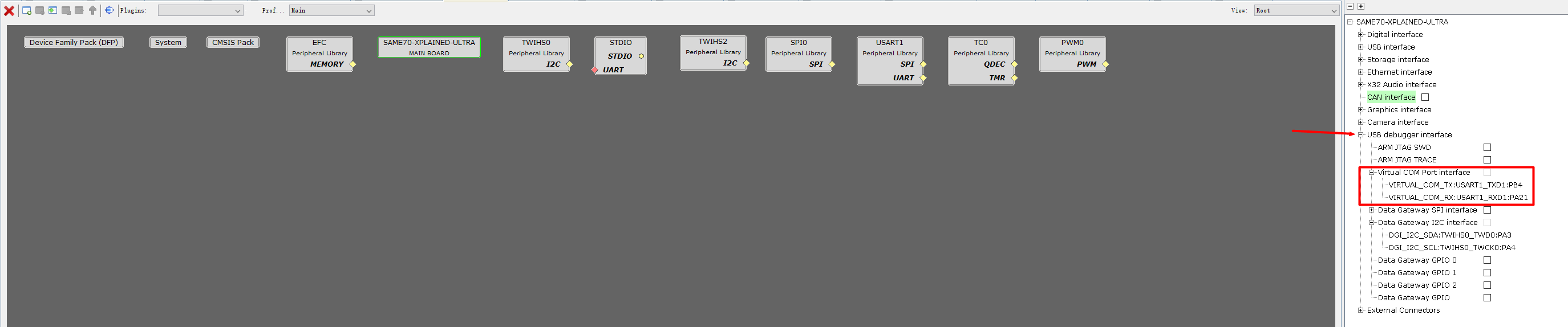
设置USART1

这里模式一共有三种可选:阻塞、非阻塞以及环形缓冲区,这里我们选择环形缓冲区,并把tx和rx的大小都设置为256
在main函数中添加以下代码:
uint8_t hello_str[] = "hello from the SAM E70 X PLAINED ultra";
int main ( void )
{
    /* Initialize all modules */
    SYS_Initialize ( NULL );
    USART1_Write(hello_str, sizeof(hello_str));

    while ( true )
    {
        LED3_Toggle();
        SYSTICK_DelayMs(500);
        /* Maintain state machines of all polled MPLAB Harmony modules. */
        SYS_Tasks ( );
    }

    /* Execution should not come here during normal operation */

    return ( EXIT_FAILURE );
}

成功实现打印。
如果我们想要通过printf就能实现串口输出,那就需要进一步设置,将串口输出重定向到标准的C库函数。
在图形配置界面,选择使能stdio工具

生成的代码中找到xc_monitor.c,这里已经实现了write和read接口,这里我们只修改输出。
在write中调用串口发送,修改后代码如下:
#include <stddef.h>
#include "peripheral/usart/plib_usart1.h"

extern int read(int handle, void *buffer, unsigned int len);
extern int write(int handle, void * buffer, size_t count);


int read(int handle, void *buffer, unsigned int len)
{
   return -1;
}

int write(int handle, void * buffer, size_t count)
{
    (void)handle;
    if (buffer == NULL || count == 0) return 0;

    USART1_Write(buffer, count);

    return (int)count;
}
此时,我们可以将main函数中的串口输出修改为我们熟悉的printf函数,修改后代码如下:
uint8_t hello_str[] = "hello from the SAM E70 X PLAINED ultra";
int main ( void )
{
    /* Initialize all modules */
    SYS_Initialize ( NULL );
    printf("%s at %s %s\r\n", hello_str, __DATE__, __TIME__);

    while ( true )
    {
        LED3_Toggle();
        SYSTICK_DelayMs(500);
        /* Maintain state machines of all polled MPLAB Harmony modules. */
        SYS_Tasks ( );
    }

    /* Execution should not come here during normal operation */

    return ( EXIT_FAILURE );
}
我们同时添加程序的编译信息,编译运行,效果如下:

至此完成了最基础的GPIO和UART基础功能,接下来将开始IIC主机、从机以及SPI等外设的上手。

有“AI”的1024 = 2048,欢迎大家加入2048 AI社区
更多推荐

 24
24 0
0- 0


 已为社区贡献3条内容

所有评论(0)