The most detailed analysis of the MCU startup process
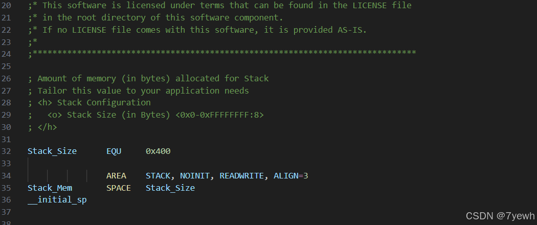
Stack_Size EQU 0x400 uses the EQU pseudo-instruction to define the size of the stack. You can think of EQU as being similar to #define in C. Here, the stack size is set to 0x400, which is 1024 bytes (1 KB).
Next, AREA STACK, NOINIT, READWRITE, ALIGN=3 declares a memory area named STACK. In ARM assembly, AREA is used to define a code section or a data section. It has several attributes after it. NOINIT means this memory area does not need to be initialized to zero at startup, because the stack is used dynamically during runtime, so initializing it is not necessary. READWRITE means this area can be read and written, so it will be placed in RAM instead of Flash. ALIGN=3 means the memory is aligned to 2³, which is 8 bytes. This alignment follows the ARM AAPCS calling convention requirement.
Stack_Mem SPACE Stack_Size uses the SPACE pseudo-instruction to actually allocate 1024 bytes of continuous memory in the STACK area defined above. The SPACE instruction simply reserves a block of memory with the specified size.
Finally, __initial_sp is a label placed after the stack memory. That means its address is the end of the stack space. Since the ARM Cortex-M uses a Full Descending stack (the stack grows from high addresses to low addresses), the stack pointer should start at the highest address of the stack region. __initial_sp is exactly this address. Later, it will be placed in the first entry of the interrupt vector table. When the chip powers on, the hardware automatically loads this value into the Main Stack Pointer (MSP) register.
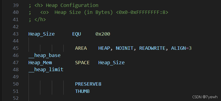
Heap_Size EQU 0x200 defines the size of the heap as 0x200, which equals 512 bytes. The heap is used by C standard library functions such as malloc() and calloc() for dynamic memory allocation. In embedded development, the heap is usually not used very often, so its default size is typically smaller than the stack.
Next, AREA HEAP, NOINIT, READWRITE, ALIGN=3 declares a memory region named HEAP, with the same attributes as the stack.
There are two labels here: __heap_base appears before the SPACE directive, so it marks the starting address of the heap; __heap_limit appears after SPACE, so it marks the ending address of the heap. These two labels are later used by the C library to determine the valid range of the heap and to prevent malloc() from allocating memory beyond its boundary.
PRESERVE8 is a pseudo-instruction that tells the assembler the stack pointer will always be kept 8-byte aligned in this file. This is required by the ARM AAPCS (ARM Architecture Procedure Call Standard). If this requirement is not met, calling certain C library functions may result in unpredictable behavior.
THUMB is a pseudo-instruction that specifies the following code should be assembled using the Thumb instruction set. The Cortex-M3 only supports the Thumb-2 instruction set (and does not support the traditional 32-bit ARM instruction set), so this line is necessary. If it is omitted, the assembler might attempt to compile the code using the ARM instruction set, which would lead to errors.
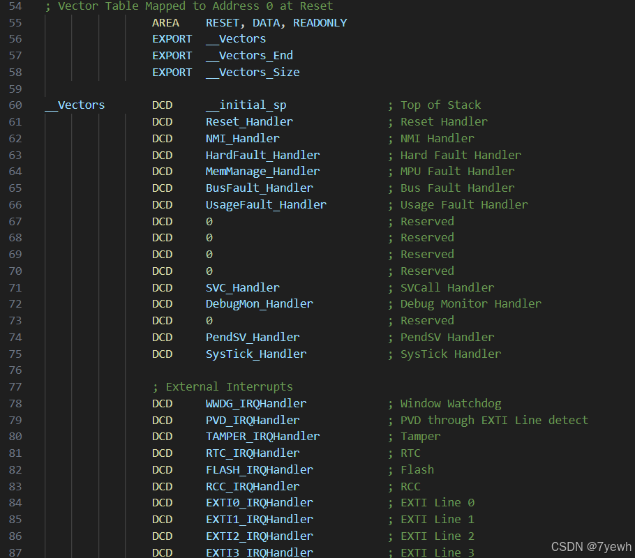
AREA RESET, DATA, READONLY declares a data section named RESET with the attribute READONLY, which means it will be placed in Flash memory. Through the linker script, this section is mapped to address 0x00000000, which is the starting address of Flash.
The following three EXPORT directives make __Vectors, __Vectors_End, and __Vectors_Size global symbols, so that other files (such as CMSIS code) can reference them to obtain the location and size of the vector table.
The vector table itself consists of a series of DCD pseudo-instructions. DCD stands for Define Constant Data, and each DCD places a 4-byte (32-bit) constant at the current location.
The first entry of the vector table is special. It is not a function address, but __initial_sp, which is the initial value of the stack pointer. The Cortex-M3 hardware specifies that upon power-on reset, the processor automatically reads the first 4 bytes from address 0x00000000 and loads it into the MSP register as the initial stack pointer.
The second entry is Reset_Handler, which is the address of the reset handler function. The hardware reads the value at address 0x00000004 and jumps to it to begin execution. That is why Reset_Handler is the true entry point of the program.
Entries three through sixteen are system exception vectors defined by the Cortex-M3 core. In order, they are:
NMI (Non-Maskable Interrupt), usually triggered by external hardware or the clock security system;
HardFault, which is the most common crash reason—when other exceptions cannot be handled or are disabled, they escalate to HardFault;
MemManage, triggered when the MPU detects an illegal memory access;
BusFault, triggered when accessing a non-existent address or when a peripheral is not properly initialized;
UsageFault, triggered by undefined instructions, division by zero, unaligned access, and similar errors.
There are four reserved entries set to 0 for future ARM use. After that come:
SVC (Supervisor Call), used by operating systems to implement system calls;
DebugMon (Debug Monitor), used by debuggers for breakpoints and monitoring;
another reserved entry;
PendSV (Pendable Service), commonly used by RTOS kernels for context switching, since its priority can be set to the lowest level so it runs after all other interrupts;
SysTick (System Tick Timer), usually configured by the HAL library to generate an interrupt every 1 ms for delay functions like HAL_Delay(), and also used by RTOS as the system time base.
Starting from the seventeenth entry are the peripheral interrupt vectors specific to the STM32F103xB. These interrupt sources are defined by ST according to the peripherals available on this particular chip model, and they vary between different STM32 devices. They include:
WWDG (Window Watchdog interrupt);
PVD (Power Voltage Detector interrupt), triggered when the supply voltage drops below a threshold;
TAMPER (tamper detection interrupt);
RTC (global RTC interrupt);
FLASH (Flash controller interrupt), triggered when a Flash erase/program operation completes or fails;
RCC (Reset and Clock Control interrupt), triggered when the clock security system detects an abnormal condition.
EXTI0 to EXTI4 correspond to external interrupt lines 0 through 4, each with its own vector. EXTI9_5 is a shared interrupt vector for lines 5 to 9, and EXTI15_10 is shared for lines 10 to 15. Since they are shared, the interrupt handler must check status flags to determine which specific line caused the interrupt.
DMA1_Channel1 through DMA1_Channel7 are the interrupts for the seven DMA1 channels, triggered when a DMA transfer completes, half-completes, or encounters an error.
ADC1_2 is a shared interrupt for ADC1 and ADC2. USB_HP_CAN1_TX is a shared vector for USB high-priority and CAN1 transmit interrupts (since on STM32F103, USB and CAN share the same SRAM buffer and cannot be used simultaneously, sharing the interrupt vector is reasonable). Similarly, USB_LP_CAN1_RX0 is shared between USB low-priority and CAN1 receive interrupts. CAN1_RX1 and CAN1_SCE are for CAN1 FIFO1 receive and CAN status change/error interrupts, respectively.
TIM1 has four separate interrupt vectors:
BRK (break interrupt, used in motor control for emergency stop),
UP (update interrupt, triggered on counter overflow),
TRG_COM (trigger and commutation interrupt),
CC (capture/compare interrupt).
TIM2, TIM3, and TIM4 each have a single interrupt vector, with all events sharing it.
I2C1 and I2C2 each have two interrupts:
EV (event interrupt, such as address match or data transfer complete),
ER (error interrupt, such as bus errors or acknowledge failure).
SPI1 and SPI2 each have one interrupt. USART1, USART2, and USART3 each have one interrupt as well.
RTC_Alarm is an interrupt generated by the RTC alarm through an EXTI line. Unlike the global RTC interrupt mentioned earlier, this one can wake the chip from standby mode. USBWakeUp is a USB wake-up interrupt, which can also wake the chip from suspend mode.
Finally, the label __Vectors_End marks the end of the vector table. __Vectors_Size EQU __Vectors_End - __Vectors automatically calculates the total size of the vector table in bytes by taking the difference between the two labels.
AREA |.text|, CODE, READONLY defines the .text section, and all following code is placed in this read-only area stored in Flash. Reset_Handler PROC marks the beginning of a function and ENDP marks its end. EXPORT Reset_Handler [WEAK] makes the symbol globally visible, and the [WEAK] attribute means that if the user defines a function with the same name in a C file, the linker will use the user’s version instead. IMPORT __main and IMPORT SystemInit work like extern declarations in C, telling the assembler that these symbols are defined in other files. SystemInit is implemented in system_stm32f1xx.c, while __main is provided by the ARM C runtime library.
Inside Reset_Handler, the instruction LDR R0, =SystemInit loads the address of SystemInit into register R0, and BLX R0 calls it while saving the return address in LR. SystemInit configures the system clock, such as selecting HSE or HSI, setting the PLL multiplier and bus prescalers, usually bringing the system clock to 72 MHz, and then returns. After that, LDR R0, =__main followed by BX R0 jumps to the C runtime entry point. Since BX does not save a return address, this is a one-way jump, meaning __main should never return and the user’s main() function is expected to run indefinitely, typically inside a while(1) loop.
The __main function performs the C runtime initialization. It copies initialized global and static variables from Flash to RAM for the .data section, clears the .bss section so that uninitialized global variables default to zero, runs any necessary C or C++ library initialization code, and finally calls the user-defined main() function.
For system exceptions, each handler such as NMI_Handler or HardFault_Handler is defined as a weak function whose body contains only B ., which means branching to the current address and forming an infinite loop. If an exception occurs and the user has not provided their own handler, the processor will get stuck in this loop. During debugging, if the program stops at such a location, it indicates which exception was triggered. Because these handlers are weak symbols, the user can override any of them simply by defining a function with the same name in a C file.
For peripheral interrupts, all interrupt handler names are weakly exported and linked to a single Default_Handler. Multiple labels are placed consecutively without any instructions between them, so they all share the same address, which points to a single B . infinite loop. If the user implements a specific interrupt handler, such as USART1_IRQHandler, the linker replaces only that one with the user’s implementation, while all other unimplemented interrupts still point to the default loop.
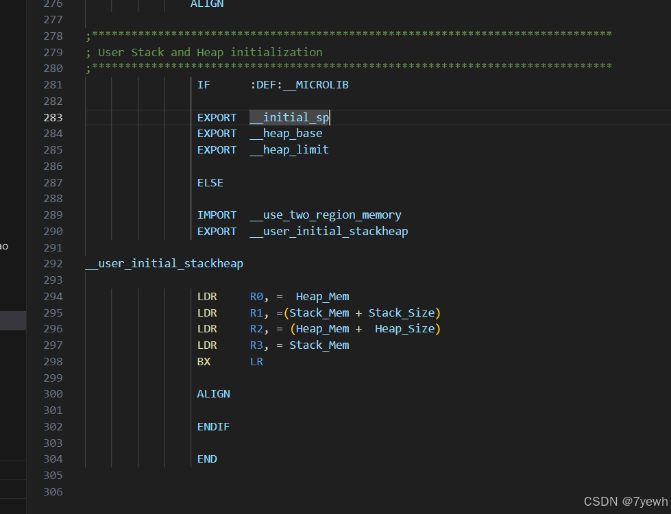
The final part handles stack and heap initialization. If __MICROLIB is defined, indicating the use of Keil’s MicroLib, only the symbols __initial_sp, __heap_base, and __heap_limit are exported, and the library uses them directly. If the standard C library is used instead, __use_two_region_memory is imported to select the two-region memory model, where stack and heap are placed in separate regions. In that case, the function __user_initial_stackheap is implemented to return the heap start, stack top, heap end, and stack bottom through registers R0 to R3 according to the ARM calling convention. The END directive marks the end of the assembly file.
Overall, when the chip powers on or resets, the Cortex-M3 hardware automatically loads the initial stack pointer from address 0x00000000 and then loads the address of Reset_Handler from 0x00000004 and jumps to it. Reset_Handler calls SystemInit to configure the clock, then jumps to __main, which initializes memory and the C runtime before calling main(). Once main() runs, it typically enters an infinite loop. When an interrupt occurs, the processor automatically saves the current context onto the stack, fetches the corresponding handler address from the vector table, and executes it. If no user-defined handler exists, the default infinite loop runs. After the interrupt handler finishes, the processor restores the saved context and resumes normal execution.

有“AI”的1024 = 2048,欢迎大家加入2048 AI社区
更多推荐
 17
17 0
0- 0


 已为社区贡献4条内容

所有评论(0)