How to Detect AC Power Failure in LED Lighting Systems Using a Discrete Transistor Circuit
$💡 :⚠️ :
AC Mains Loss Detection for LED Drivers: A Simple BJT-Based Circuit with LTspice Validation
Why Detect AC Power Loss?
In smart lighting and emergency backup systems, knowing when the AC mains power fails is critical. For example:
- An emergency LED driver may need to switch to battery mode within milliseconds.
- A DALI or 0–10V controller might want to log a “power outage” event.
- Some safety-critical luminaires must shut down gracefully to avoid flicker or surge damage.
But how do you reliably detect that the AC input has disappeared—especially when your control logic runs on a low-voltage DC rail (e.g., 5V or 3.3V)?
This article presents a low-cost, discrete solution using a full-wave rectifier, a Zener diode, and an NPN transistor to generate a clean “mains present” signal. We’ll walk through the circuit operation and validate it with SIMetrix simulation.
How It Works: From AC Input to MCU Logic Level
The core idea is elegant:
Use a Zener diode as a voltage threshold detector. When AC is present, the rectified voltage exceeds the Zener breakdown → transistor turns ON → output = LOW. When AC drops below threshold, transistor turns OFF → output = HIGH.
Let’s break it down step by step.
🔹 Normal Operation (Mains Present)
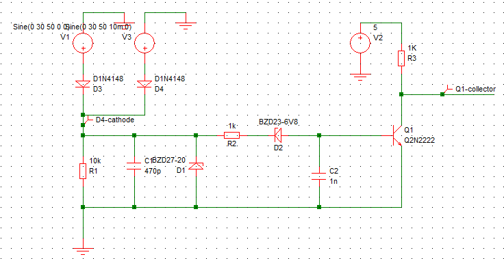
- The AC input (e.g., 30V peak from a transformer or resistive divider from L/N) is fed into a full-wave rectifier (D3/D4).
- The rectified full-wave sine is filtered slightly by C1, creating a pulsating DC voltage with a peak near 30V × √2 ≈ 42V.
- This high voltage passes through R1 and reaches the cathode of D2 (6.8V Zener).
- Since 42V ≫ 6.8V, the Zener breaks down and clamps its cathode to ~6.8V.
- This 6.8V appears at the base of Q1 (NPN).
- With emitter grounded, $ V_{BE} = 6.8V \gg 0.7V $ → Q1 saturates fully ON.
- Q1’s collector is pulled to near ground → output signal = ~0V.
- The MCU reads this as: “Mains OK — no action needed.”
🔹 Power Loss Condition (Mains Fails)
- When AC input drops (e.g., blackout), the rectified voltage decays.
- Once it falls below the Zener breakdown voltage (~6.8V + diode drop), the Zener stops conducting.
- Q1’s base voltage collapses to <0.5V → Q1 turns OFF.
- The pull-up resistor R3 (10kΩ) now pulls the output to +5V.
- The MCU sees a HIGH signal and interprets it as: “Mains lost! Save data / switch to backup!”
📌 Logic Convention:
- Output = LOW (0V) → Mains present
- Output = HIGH (5V) → Mains lost
This active-low sensing is common in fault-monitoring circuits.
🔹 Critical Design Rule: Zener Voltage Selection
As you correctly pointed out:
The Zener voltage determines when the circuit triggers.
For example:
- If you want to detect when AC drops to 10V RMS, then:
- Peak voltage = 10V × √2 ≈ 14.1V
- After rectification and filtering, the DC voltage ≈ 14V
- To ensure reliable detection, choose a Zener with V_Z ≥ 14.1V + 0.7V (V_BE drop) = ~14.8V
- So pick a 15V Zener (e.g., BZD23-C15)
✅ Rule of Thumb:
Choose Zener voltage such that:
$$
V_Z > V_{\text{min_AC}} \times \sqrt{2} + 0.7V
$
where $ V_{\text{min_AC}} $ is the minimum AC voltage you consider “normal”.
And remember:
Always include margin — noise, temperature drift, component tolerance can affect performance.
Test in real hardware!
Thus, your choice of Zener is not arbitrary — it defines the detection threshold.
💡 Example:
- Want to trigger at 5V RMS? → V_peak = 7.07V → Pick Zener ≥ 7.8V
- Want to trigger at 230V RMS? → V_peak = 325V → Use a 330V Zener or resistive divider + lower-voltage Zener
🔹 Role of Key Components
| Component | Function |
|---|---|
| R1 | Limits current into the Zener; sets detection sensitivity. In real applications, R1 may be part of a high-voltage resistive divider from L/N to scale 230V/120V down to a safe level (~30V). |
| D2 (6.8V Zener) | Acts as the voltage threshold. Choose based on desired dropout margin (e.g., 5.1V for tighter detection, 10V for noise immunity). |
| Q1 (NPN) | Functions as a switch, not an amplifier. Saturation ensures clean logic levels. |
| R3 (10kΩ) | Pull-up to MCU logic rail (5V or 3.3V). Ensures defined HIGH state when Q1 is off. |
| C1 | Small filter to reduce ripple-induced false triggering. Too large → slows response. |
⚠️ Critical Design Warning:
The current through the Zener must be limited by R1 to avoid thermal runaway.
Example: If rectified DC = 30V, Zener = 6.8V, then max current ≈ (30V – 6.8V) / R1.
For R1 = 10kΩ → I ≈ 2.3 mA (safe for BZD23 series).
But if R1 is too small (e.g., 1kΩ), I = 23 mA → may overheat or destroy the Zener!
Thus, R1 is not just a resistor—it’s a safety fuse.
Simulation Results: Validating the Detection Logic
Figure 2 shows the transient response of the circuit under normal AC operation:
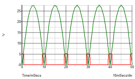
- Green curve: The rectified AC voltage (after D3/D4 and C1) — a pulsating DC waveform with peak ~25V, frequency 100Hz (from 50Hz input).
- Red line: The output signal at Q1’s collector — a clean digital square wave.
🔹 What This Tells Us
- During each half-cycle, the rectified voltage rises to ~25V → exceeds the Zener breakdown voltage (~6.8V) → Zener conducts → Q1 turns ON → output = 0V
- Near the zero-crossing point, the rectified voltage drops below the Zener threshold → Zener stops conducting → Q1 turns OFF → output = 5V
- Result: The output toggles between 0V and 5V at 100Hz — but this is not a fault signal; it’s just ripple-induced switching.
⚠️ Important Note:
In real applications, you want only one state when mains is present:
- Output should stay LOW as long as AC voltage > threshold
- Only go HIGH when AC drops below threshold (e.g., blackout)
So why does the output flicker? Because:
- The rectified voltage dips below Zener threshold during every zero-crossing
- But in reality, the capacitor C1 holds charge, so the voltage doesn’t drop to zero — only to ~5–7V
- If your Zener is 6.8V, then at every zero-crossing, the Zener may briefly stop conducting → Q1 turns off → output spikes to 5V
This means:
❌ The circuit is not suitable for detecting AC loss if used directly — it will generate false alarms due to AC ripple.
🔸 How to Fix It: Add Hysteresis or Use a Smaller Capacitor
To prevent false triggering:
- Reduce C1 (e.g., from 10µF to 1µF) → faster discharge → less time below threshold
- Or add a Schmitt trigger (e.g., with comparator IC) to introduce hysteresis
- Or use a higher Zener voltage (e.g., 10V) and accept slower response
But for true mains loss detection, we need:
- A larger C1 (e.g., 100µF) to hold charge longer
- And wait for full AC dropout before triggering
Thus, this simulation shows the raw behavior, but real-world design requires filtering or logic enhancement.
Conclusion
This simple BJT-based circuit demonstrates how to convert the presence or absence of AC mains voltage into a clean digital signal for microcontroller monitoring—using only a rectifier, a Zener diode, and a transistor. Its elegance lies in its minimalism: no ICs, no isolated power supplies, just fundamental semiconductor behavior.
However, as your simulation and practical insight reveal, the devil is in the details:
-
The Zener voltage is not arbitrary—it directly sets your detection threshold.
Want to trigger at 10V RMS? Choose a Zener ≥ 10.7V (accounting for the transistor’s ~0.7V base-emitter drop).
Always include margin for component tolerance, temperature drift, and noise. -
Ripple from rectified AC can cause false toggling, especially with small filter capacitors. In real systems, you may need additional filtering, hysteresis, or software debouncing to distinguish true power loss from normal zero-crossings.
-
Most importantly: simulate, then validate on the bench. LTspice shows ideal behavior—but only hardware testing under brownout, surge, and temperature extremes reveals true reliability.
This approach won’t replace optocouplers in safety-critical SELV applications, but for cost-sensitive, non-isolated LED drivers or smart controllers, it offers an excellent balance of simplicity, speed, and functionality.
🔧 Final Tip: Start with a 6.8V or 10V Zener for low-voltage prototypes, then scale up using resistive dividers for 120V/230V systems. Measure the Zener current—never let it exceed its power rating!
With careful design and real-world validation, this humble circuit can be the “watchdog” that keeps your lighting system intelligent—even when the lights go out.

有“AI”的1024 = 2048,欢迎大家加入2048 AI社区
更多推荐


 27
27 0
0- 0


 已为社区贡献1条内容

所有评论(0)