QEMU/KVM Device Passthrough详解
本文主要探讨了Qemu/KVM中PCI设备直通的技术实现,重点分析了Virtio协议、IOMMU机制和VFIO框架。文章首先介绍了PCI设备的枚举和配置过程,包括config space访问机制。在IOMMU部分,深入讲解了Intel VT-d技术的实现,包括地址转换、中断重映射和中断投递机制。最后,文章详细解析了VFIO框架的工作原理,包括driver override、container/gr
概述
Qemu/KVM Guest中的设备,大多是基于Virtio协议的模拟设备,例如:virtio-blk,virtio-scsi,virtio-net等,后端可以是qemu或者是通过vhost-user接入的其他应用(例如dpdk、spdk),参考下图

但是,无论是哪一种,Guest都是通过virtio协议与模拟软件通信,然后通过模拟软件与设备通信。
设备直通,便是让Guest直接与设备通信交互,如下:
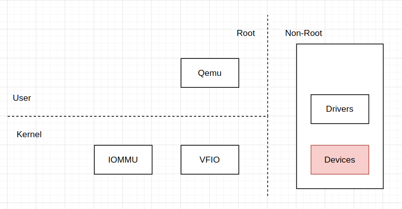
接下来,我们将以pci device passthrough为例,讨论设备直通是如何实现的;不过在此之前,我们可以先简单讨论与设备直通有关的几个问题:
- pci设备是如何被guest识别出来的?
- guest如何访问pci设备的config space和bars
- pci设备如何对GPA做DMA
- pci设备如何将中断发送给Guest
QEMU/VFIO解决的是问题1/2,IOMMU解决的是问题3/4。
PCI Device
PD.1 PCI Device枚举
一台宿主机是如何识别出一个pci设备的呢?首先参考一段Wikipedia,
 https://en.wikipedia.org/wiki/PCI_configuration_space#Bus_enumeration
When the computer is powered on, the PCI bus(es) and device(s) must be enumerated by BIOS or operating system. Bus enumeration is performed by attempting to access the PCI configuration space registers for each buses, devices and functions. Note that device number, different from VID and DID, is merely a device's sequential number on that bus.
If no response is received from the device's function #0, the bus master performs an abort and returns an all-bits-on value (FFFFFFFF in hexadecimal), which is an invalid VID/DID value, thus the BIOS or operating system can tell that the specified combination bus/device_number/function (B/D/F) is not present.
参考以下代码:
pci_legacy_init()
  -> pcibios_scan_root()
	-> pci_scan_root_bus() // pci_root_ops
	  -> pci_bus_insert_busn_res(b, bus, 255);
	  -> pci_scan_child_bus()
	    -> pci_scan_child_bus_extend()
	       ---
			for (devfn = 0; devfn < 256; devfn += 8) {
				nr_devs = pci_scan_slot(bus, devfn);
				...
		   ---
	        -> pci_scan_single_device()
			  -> pci_scan_device()

pci_scan_device()
---
	// If cannot get any thing from vendor id, it's saying no device on this slot
	if (!pci_bus_read_dev_vendor_id(bus, devfn, &l, 60*1000))
		return NULL;

	dev = pci_alloc_dev(bus);
	...
	dev->devfn = devfn;
	dev->vendor = l & 0xffff;
	dev->device = (l >> 16) & 0xffff;

	if (pci_setup_device(dev)) {
		...
	}
---

pci_bus_read_dev_vendor_id()
  -> pci_bus_generic_read_dev_vendor_id()
     ---
	if (pci_bus_read_config_dword(bus, devfn, PCI_VENDOR_ID, l))
		return false;

	/* Some broken boards return 0 or ~0 if a slot is empty: */
	if (*l == 0xffffffff || *l == 0x00000000 ||
	    *l == 0x0000ffff || *l == 0xffff0000)
		return false;
	 ---
	   -> pci_bus_read_config_dword()
	     -> pci_root_ops.read()
		    pci_read()
			  -> raw_pci_read()
			     ---
				if (domain == 0 && reg < 256 && raw_pci_ops)
					return raw_pci_ops->read(domain, bus, devfn, reg, len, val);
				if (raw_pci_ext_ops)
					return raw_pci_ext_ops->read(domain, bus, devfn, reg, len, val);
				 ---
这需要着重说明的是,如何读取config space,在raw_pci_read()中,有两个结构体,
- raw_pci_ops,
- raw_pci_ext_ops,
参考函数:
pci_arch_init()
  -> pci_direct_probe() // ioport 0xcf8/0xcfc
	 ---
		if (!request_region(0xCF8, 8, "PCI conf1"))
			goto type2;

		if (pci_check_type1()) {
			raw_pci_ops = &pci_direct_conf1; // out/in instructions
			port_cf9_safe = true;
			return 1;
		}
	 ---
  -> pci_mmcfg_early_init()
	 ---
		if (pci_mmcfg_check_hostbridge()) // check some specific platfrom
			known_bridge = 1;
		else
			acpi_table_parse(ACPI_SIG_MCFG, pci_parse_mcfg);
			  -> pci_mmconfig_add()
	             ---
					pr_info(PREFIX
					       "MMCONFIG for domain %04x [bus %02x-%02x] at %pR "
					       "(base %#lx)\n",
					       segment, start, end, &new->res, (unsigned long)addr);
					for example:
						PCI: MMCONFIG for domain 0000 [bus 00-ff] at [mem 0x80000000-0x8fffffff] (base 0x80000000)
				 ---
		__pci_mmcfg_init(1);
		  -> check list_empty(&pci_mmcfg_list), if empty, quit
	      -> pci_mmcfg_arch_init()
	        -> raw_pci_ext_ops = &pci_mmcfg;
	 ---
由此可知,
- raw_pci_ops对应的是ioport 0xcf8/0xcfc,对pci config space进行读写,而且,其仅能读写0~255,对应的是PCI;
- raw_pci_ext_ops则对应的是mmcfg,通过线性地址直接访问pci config space,对应的是PCIe
需要特别说明的是,参考pci_mmcfg_early_init,pci mmcfg空间的地址可以通过两种方式获得:
- pci_mmcfg_check_hostbridge(),特殊平台的特殊方法
- ACPI ACPI_SIG_MCFG通用方法
PD.2 PCI Device Setup
在pci device被创建之后,通过pci_dev这个结构,它会初始化两个关键数据:
- bars,其中包括了与设备交互,
- capbility,用于获取设备的配置信息,
pci_scan_single_device()
  -> pci_scan_device()
    -> pci_setup_device()
	  -> pci_read_bases() // fill the pdev->resource[], we can get bar address and size
  -> pci_device_add()
	-> pci_init_capabilities()
pci_read_bases()会填充pci_dev->resource[],也就是pci config space中的bars的地址和长度;方法为:
- 保存原始值:备份BAR寄存器原始内容。
- 写入全1:向BAR写入0xFFFFFFFF。
- 读回值:读取BAR值,低位标志位保持不变,高位返回设备要求的地址掩码。
- 计算大小:
size_mask = read_value & (is_io ? ~0x3 : ~0xF); // 掩码去除标志位
size = (~size_mask) + 1;  // 取反加1得到大小
设备的配置信息保存在pci config space中cap list中,
| Feature | cap list | extend cap list |
| Start | cap_ptr 0x34 | fixed at 0x100 |
| ID Bits | 8 | 16 |
| Next bytes: | 1 | 2 |
| Function | PM, MSI, MSIx | AER, VC, SR-IOV |
| Range | 0~256 | 256~4096 |
pci config space中,cap都是以list的形式保存的,查询某个cap,其实就是找到这个cap在pci config space中的偏移,
pci_init_capabilities()
  -> pci_msix_init()
    -> dev->msix_cap = pci_find_capability(dev, PCI_CAP_ID_MSIX);
	  -> __pci_bus_find_cap_start() // cap ptr
      -> __pci_find_next_cap()
        -> __pci_find_next_cap_ttl()

the dev->msix_cap include id and next
IOMMU
参考文献
IM.1 intel_iommu=on iommu=pt
要使用IOMMU,在Intel平台上,开启方法是,在内核command line上加入intel_iommu=on iommu=pt,那么它代表的是什么?
iommu_setup()
---
		if (!strncmp(p, "pt", 2))
			iommu_set_default_passthrough(true);
			  -> iommu_def_domain_type = IOMMU_DOMAIN_IDENTITY;
				// DMA addresses are system physical addresses
---
iommu=pt将iommu_def_domain_type设置为IOMMU_DOMAIN_IDENTITY;
intel_iommu_setup()
---
		if (!strncmp(str, "on", 2)) {
			dmar_disabled = 0;
			pr_info("IOMMU enabled\n");
		}
---
intel_iommu=on会让intel iommu的硬件开启,参考以下代码:
intel_iommu_init()
---
	if (no_iommu || dmar_disabled) {
		            ^^^^^^^^^^^^^^^^
		...
		if (intel_iommu_tboot_noforce) {
			for_each_iommu(iommu, drhd)
				iommu_disable_protect_mem_regions(iommu);
		}
		...
		intel_disable_iommus();
		goto out_free_dmar;
	}
	...
	ret = init_dmars();
	...
	bus_set_iommu(&pci_bus_type, &intel_iommu_ops);
	  -> bus->iommu_ops = intel_iommu_ops;
	                      ^^^^^^^^^^^^^^^
	  -> iommu_bus_init()
	    -> nb->notifier_call = iommu_bus_notifier;
		   -> iommu_probe_device()
			 -> __iommu_probe_device()
	         -> probe_alloc_default_domain()
		-> bus_register_notifier(bus, nb)
		-> bus_iommu_probe()
	      -> probe_alloc_default_domain()

	...
	for_each_iommu(iommu, drhd) {
		if (!drhd->ignored && !translation_pre_enabled(iommu))
			iommu_enable_translation(iommu);

		iommu_disable_protect_mem_regions(iommu);
	}
---
在intel iommu启动过程中的各个关键函数会在接下来一一解析。
申请默认的iommu domain, 已知iommu_def_domain_type已经被iommu=pt设置为IOMMU_DOMAIN_IDENTITY
probe_alloc_default_domain()
---
   if (!gtype.type)
   	gtype.type = iommu_def_domain_type;

   iommu_group_alloc_default_domain(bus, group, gtype.type);
     -> __iommu_domain_alloc()
	   -> bus->iommu_ops->domain_alloc(type)
	     -> intel_iommu_domain_alloc()
	        ---
				...
				case IOMMU_DOMAIN_IDENTITY:
					return &si_domain->domain;
				...
			---
---
这里有两个问题:
- si_domain是做什么的?
- default domain是做什么的?
/*
 * This domain is a statically identity mapping domain.
 *	1. This domain creats a static 1:1 mapping to all usable memory.
 * 	2. It maps to each iommu if successful.
 *	3. Each iommu mapps to this domain if successful.
 */
static struct dmar_domain *si_domain;
si_domain的注释已经解释的很清楚了,它的创建过程参考:
intel_iommu_init()
  -> init_dmars()
	-> si_domain_init()
	   ---
	for_each_online_node(nid) {
		unsigned long start_pfn, end_pfn;
		int i;

		for_each_mem_pfn_range(i, nid, &start_pfn, &end_pfn, NULL) {
			ret = iommu_domain_identity_map(si_domain,
					mm_to_dma_pfn(start_pfn),
					mm_to_dma_pfn(end_pfn));
			if (ret)
				return ret;
		}
	}
	   ---
默认情况下,每个设备再被创建时,都会默认创建一个iommu group,同时默认加入到default domain里,
The sequence is:
iommu_probe_device()
  -> __iommu_probe_device() // Get a group
	-> iommu_group_get_for_dev()
	  -> ops->device_group()
	    -> intel_iommu_device_group()
	      -> pci_device_group()
	        -> iommu_group_alloc()
      -> iommu_group_add_device()
  -> iommu_alloc_default_domain(group, dev) // Get a domain, identity by default
  -> __iommu_attach_device(group->default_domain, dev) // attach to the default domain
IM.2 DMA Remapping
在DMA Remapping中,存在两个mapping:
- device -> domain,这里domain其实对应了一个iommu地址空间,其中包含的是一个页表,
- IOVA -> HPA,也就是domain中的页表
以下是intel-vtd-spec中给出的表的结构,其中包含了这两个mapping,
PCI Device to Domain Mapping
Legacy Mode, no PASID support.
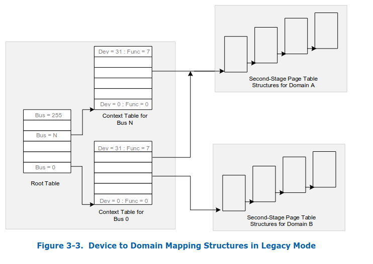
Scable-Mode, support PASID,

Scalable-mode context-entries support both requests-without-PASID and requests-with-PASID. However unlike legacy mode, in scalable-mode, requests-without-PASID obtain a PASID value from the RID_PASID field of the scalable-mode context-entry and are processed similarly to rly to requests-with-PASID.
两种mapping对应的内核代码参考以下,这里使用的vfio上下文
device -> domain
intel_iommu_init()
  -> init_dmars()
    -> iommu_set_root_entry()

iommu_set_root_entry()
---
	addr = virt_to_phys(iommu->root_entry);
	...
	dmar_writeq(iommu->reg + DMAR_RTADDR_REG, addr);
	...
	writel(iommu->gcmd | DMA_GCMD_SRTP, iommu->reg + DMAR_GCMD_REG);

	/* Make sure hardware complete it */
	IOMMU_WAIT_OP(iommu, DMAR_GSTS_REG,
		      readl, (sts & DMA_GSTS_RTPS), sts);
	...
---


vfio_group_set_container()
vfio_ioctl_set_iommu()
  -> __vfio_container_attach_groups()
	-> ops->attach_group()
	  -> vfio_iommu_type1_attach_group()
	    -> iommu_attach_group()
	       ^^^^^^^^^^^^^^^^^^^^
	      -> __iommu_attach_group()
	        -> iommu_group_do_attach_device()
	          -> iommu_attach_device()
	            -> intel_iommu_attach_device()
	              -> domain_add_dev_info()
	                -> dmar_insert_one_dev_info()
	                  -> domain_attach_iommu()
	                    -> domain_context_mapping()
	                      -> domain_context_mapping_one()

domain_context_mapping_one()
---
	...
	// bus/dev -> context (domain)
	context = iommu_context_addr(iommu, bus, devfn, 1);
	...
	context_set_domain_id(context, did);
	...
---

iommu_context_addr()
---
	struct root_entry *root = &iommu->root_entry[bus];
	...
	if (*entry & 1)
		context = phys_to_virt(*entry & VTD_PAGE_MASK);
	else {
		...
		context = alloc_pgtable_page(iommu->node);
		...
		__iommu_flush_cache(iommu, (void *)context, CONTEXT_SIZE);
		phy_addr = virt_to_phys((void *)context);
		*entry = phy_addr | 1;
		__iommu_flush_cache(iommu, entry, sizeof(*entry));
	}
	return &context[devfn];
---
IOVA -> HPA
vfio_iommu_type1_ioctl()
  -> vfio_iommu_type1_map_dma()
	-> vfio_dma_do_map()
	  -> vfio_pin_map_dma()
	    -> vfio_pin_pages_remote()
	      -> vaddr_get_pfns()
	        -> pin_user_pages_remote()

vfio_iommu_map()
  -> iommu_map()
	^^^^^^^^^^^^
	-> __iommu_map()
	  -> __iommu_map_pages()
	    -> intel_iommu_map_pages()
	      -> intel_iommu_map()
	        -> __domain_mapping()
	          -> pte = pfn_to_dma_pte(domain, iov_pfn, &largepage_lvl);
			    -> parent = domain->pgd;
IM.3 Interrupt Remapping
Interrupt Remmapping引入了两个主要修改,
一个是interrupt request格式变化,参考下图:

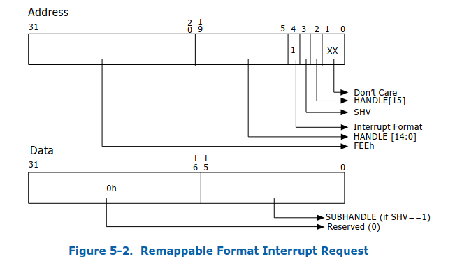
其中address中bit4,如果是0,就代表address和data都是compatibility格式,如果是1,就是remappable格式;另一个是interrupt remapping table;之后,message signal interrupt的过程就变成下图:
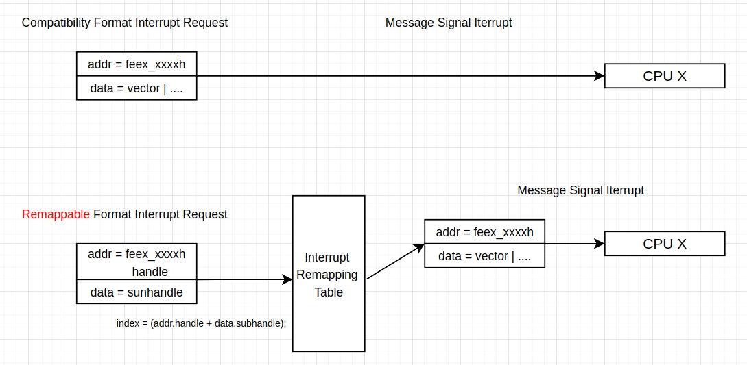
interrupt remapping是基础,引入之后,开发者就可以在interrupt remapping table的entry上做文章,并且在这里加入新的机制,例如下一小节的interrupt posting功能。
IM.4 Interrupt Posting
介绍interrupt posting之前,我们需要回忆一下,Posted-interrupt proccessing,参考链接:
- posted-interrupt notification vector
- Posted-interrupt Descirptor
工作流程如下:
- vcpu给自己的vmcs设置一个合理的posted-interrupt notification vector,我们称之为NV
- 当我们通过IPI机制,给该vcpu所在的物理cpu发送V vector时,会触发该CPU的posted-interrupt processing机制
- posted-interrupt processing机制被触发之后,硬件自动将Posted-interrupt-Descirptor.PIR的值OR进vcpu的VIRR,然后进入virtual-interrrupt delivery机制
Posted-interrupt Descriptor,格式如下:
/* Posted-Interrupt Descriptor */
struct pi_desc {
	u32 pir[8];     /* Posted interrupt requested */
	union {
		struct {
				/* bit 256 - Outstanding Notification */
			u16	on	: 1,
				/* bit 257 - Suppress Notification */
				sn	: 1,
				/* bit 271:258 - Reserved */
				rsvd_1	: 14;
				/* bit 279:272 - Notification Vector */
			u8	nv;
				/* bit 287:280 - Reserved */
			u8	rsvd_2;
				/* bit 319:288 - Notification Destination */
			u32	ndst;
		};
		u64 control;
	};
	u32 rsvd[6];
} __aligned(64);
其中关键的域是:
- PIR,265bits,每一个vector对应一个bit
- NV,这个与vmcs中的posted-interrupt notification vector不同
- SN,如果设置了,非紧急IR不会发送NV
- NDST,the physical APIC-ID of the destination logical processor for the notification event
NV和NDST为Interrupt posting机制使用。
为支持interrupt posting,在Interrupt remapping table的IRTE,对比remappable IRTE,,增加了以下信息

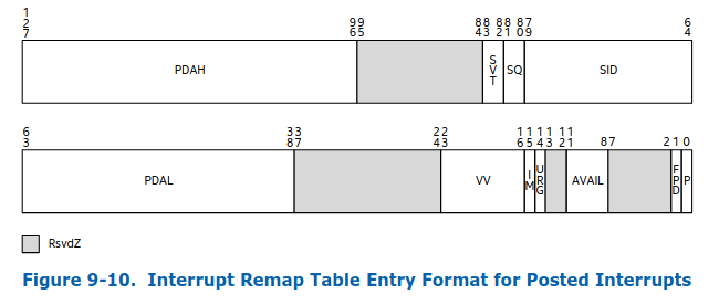
- PDAH: Posted Descriptor Address Hig
- PDAL: Posted Descriptor Address Low
- VV: Virtual Vector
参考:5.2.3 Interrupt-Posting Hardware Operation
Set bit in PIR corresponding to the Vector field value from the IR,
generate a notification event (interrupt) with attributes as follows:
- NSDT field specifies the physical APIC-ID of destination logical CPU
- NV field specifies the vector to be used for the notification interrupt to signal the destination CPU about pending posted interrupt
硬件工作流程中的关键步骤如下:
- 根据Interrupt Remapping的步骤,找到IRTE,
- 根据IRTE.PDAH | IRTE.PDAL,获取Posted-interrupt Descriptor的地址,以下简称PD
- 设置PD.PIR中IRTE.VV相关bit
- 向PD.NDST对应的物理cpu发送PD.NV vector,即posted-interrupt notification vector
- 对应cpu会触发posted-interrupt processing机制
这里有个关键点:需要向特定的物理cpu发送IPI,这个物理cpu通常是vcpu运行的那个,但是下面两种情况如何处理?
- vcpu thread被调度到其他cpu
- vcpu halt,进入vcpu_block(),开始sleep
首先看下调度的场景,参考代码:
kvm_sched_in()
  -> kvm_arch_vcpu_load()
    -> vmx_vcpu_pi_load()

vmx_vcpu_pi_load()
---
	struct pi_desc *pi_desc = vcpu_to_pi_desc(vcpu);
	...
	/* The full case.  */
	do {
		old.control = new.control = pi_desc->control;

		dest = cpu_physical_id(cpu);

		if (x2apic_mode)
			new.ndst = dest;
		else
			new.ndst = (dest << 8) & 0xFF00;

		new.sn = 0;
	} while (cmpxchg64(&pi_desc->control, old.control,
			   new.control) != old.control);
---

kvm_sched_out()
---
	if (current->on_rq) {
		WRITE_ONCE(vcpu->preempted, true);
		...
	}
	kvm_arch_vcpu_put(vcpu)
      -> vmx_vcpu_put()
        -> vmx_vcpu_pi_put()
	...
---

vmx_vcpu_pi_put()
---
	/* Set SN when the vCPU is preempted */
	if (vcpu->preempted)
		pi_set_sn(pi_desc);

--
在调度到一个cpu上之后,会将该cpu的id更新到PD里;如果vcpu被抢占,PD的SN会被清掉,与该vcpu相关的interrupt posting不会再发送NV,posted-interrupt processing将由cpu_enter_guest()调用static_call_cond(kvm_x86_sync_pir_to_irr)触发。
接下来看vcpu halt的场景,
vcpu_block()
  -> kvm_x86_ops.pre_block()
	 vmx_pre_block()
	   -> pi_pre_block()


pi_pre_block()
---
	if (!WARN_ON_ONCE(vcpu->pre_pcpu != -1)) {
		vcpu->pre_pcpu = vcpu->cpu;
		list_add_tail(&vcpu->blocked_vcpu_list,
			      &per_cpu(blocked_vcpu_on_cpu,
				       vcpu->pre_pcpu));
		...
	}
	...
	do {
		old.control = new.control = pi_desc->control;
		...
		/*
		 * Since vCPU can be preempted during this process,
		 * vcpu->cpu could be different with pre_pcpu, we
		 * need to set pre_pcpu as the destination of wakeup
		 * notification event, then we can find the right vCPU
		 * to wakeup in wakeup handler if interrupts happen
		 * when the vCPU is in blocked state.
		 */
		dest = cpu_physical_id(vcpu->pre_pcpu);


		if (x2apic_mode)
			new.ndst = dest;
		else
			new.ndst = (dest << 8) & 0xFF00;

		/* set 'NV' to 'wakeup vector' */
		new.nv = POSTED_INTR_WAKEUP_VECTOR;
	} while (cmpxchg64(&pi_desc->control, old.control,
			   new.control) != old.control);
...
---

DEFINE_IDTENTRY_SYSVEC(sysvec_kvm_posted_intr_wakeup_ipi)
{
	ack_APIC_irq();
	inc_irq_stat(kvm_posted_intr_wakeup_ipis);
	kvm_posted_intr_wakeup_handler();
}


pi_wakeup_handler()
---
	list_for_each_entry(vcpu, &per_cpu(blocked_vcpu_on_cpu, cpu),
			blocked_vcpu_list) {
		struct pi_desc *pi_desc = vcpu_to_pi_desc(vcpu);

		if (pi_test_on(pi_desc) == 1)
			kvm_vcpu_wake_up(vcpu);
	}
---
在vcpu进入halt状态,vcpu_block()函数会将PD.NV设置为POSTED_INTR_WAKEUP_VECTOR,后续interrupt posting机制将给对应物理cpu发送POSTED_INTR_WAKEUP_VECTOR,相关处理函数会唤醒相关vcpu。
VFIO-PCI
这里我们仅关注,vfio-pci部分内容。
VP.1 driver override
在设备透传之前,我们需要现将设备交给vfio,其操作步骤如下:
sudo sh -c "echo 0000:01:00.0 > /sys/bus/pci/devices/0000:01:00.0/driver/unbind"
sudo sh -c "echo vfio-pci > /sys/bus/pci/devices/0000:01:00.0/driver_override"
sudo sh -c "echo 0000:01:00.0 > /sys/bus/pci/drivers/vfio-pci/bind"
在内核中,其对应的操作为:
drivers/base/bus.c
unbind_store()
  -> device_driver_detach()
    -> device_release_driver_internal()
	  -> __device_release_driver()
	    -> drv->remove()

drivers/pci/pci-sysfs.c
driver_override_store()
---
	device_lock(dev);
	old = pdev->driver_override;
	if (strlen(driver_override)) {
		pdev->driver_override = driver_override;
	} else {
		kfree(driver_override);
		pdev->driver_override = NULL;
	}
	device_unlock(dev);
---

drivers/base/bus.c
bind_store()
  -> driver_match_device()
	-> pci_match_device()
	   ---
	/* When driver_override is set, only bind to the matching driver */
	if (dev->driver_override && strcmp(dev->driver_override, drv->name))
		return NULL;
	   ---
  -> device_driver_attach
过程较为简单。
这里不得不赞叹以下device-driver架构的优雅,其不仅仅包含了device和driver的联结,还有device和driver的解耦。driver决定的是如何操作设备,而非设备本身,例如,某系网卡,driver可以将它塑造成一个Ethernet网卡,但也可以是一个iscsi initiator。
VP.2 container & group
这是vfio中的三个概念,分别对应了三个fops
- container,vfio_fops,
- group,vfio_group_fops,
- device,vfio_device_fops,
本小节,我们只看下container & group,它们分别对应了iommu的domain和group,主要是为了实现DMA Remapping,举个例子:设备发送给设备的sglist中,保存的地址都是物理地址,对应guest就是GPA,那么设备在执行DMA的时候,使用的地址也就是GPA,此时DMA Remapping会将次GPA转换为HPA,从IM.2 DMA Remapping中,我们了解到,这里存在device -> domain、IOVA(GPA) -> HPA两个地址转换,接下来我们看下这两个mapping是如何建立的。
vfio_group_fops,
vfio_init()
---
	...
	/* /dev/vfio/$GROUP */
	vfio.class = class_create(THIS_MODULE, "vfio");
	...
	ret = alloc_chrdev_region(&vfio.group_devt, 0, MINORMASK + 1, "vfio");
	...
	cdev_init(&vfio.group_cdev, &vfio_group_fops);
	ret = cdev_add(&vfio.group_cdev, vfio.group_devt, MINORMASK + 1);
	...
---

The cdev of vfio_group_fops is created when:
vfio_pci_probe()
  -> vfio_init_group_dev(&vdev->vdev, &pdev->dev, &vfio_pci_ops);
  -> vfio_register_group_dev()
	-> iommu_group = iommu_group_get(device->dev)
	-> vfio_create_group()
	   ---
		group->iommu_group = iommu_group;
		...
		minor = vfio_alloc_group_minor(group);
		...
		// It should be under /dev/vfio/<group id>
		dev = device_create(vfio.class, NULL,
				    MKDEV(MAJOR(vfio.group_devt), minor),
				    group, "%s%d", group->noiommu ? "noiommu-" : "",
			    	iommu_group_id(iommu_group));
	   ---
    -> list_add(&device->group_next, &group->device_list);
接下来,我们便可以通过ioctl操作/dev/vfio/<group id>,其中最关键的两个命令为:
VFIO_GROUP_GET_DEVICE_FD
vfio_group_get_device_fd()
---
	...
	device = vfio_device_get_from_name(group, buf);
	...
	filep = anon_inode_getfile("[vfio-device]", &vfio_device_fops, device, O_RDWR)
	...                                               ^^^^^^
---
VFIO_GROUP_SET_CONTAINER:
vfio_group_set_container()
---
    f = fdget(container_fd);
    ...
    if (f.file->f_op != &vfio_fops) {
                         ^^^^^^^^
        fdput(f);
        return -EINVAL;
    }
    ...
    container = f.file->private_data;
    ...
    driver = container->iommu_driver;
    if (driver) {
        ret = driver->ops->attach_group(container->iommu_data,
                        group->iommu_group);
              vfio_iommu_type1_attach_group()
              -> iommu_domain_alloc()
              -> vfio_iommu_attach_group()
                -> iommu_attach_group()
        ...
    }
---
这里分别引入了device和container,我们先看下container,其对应的设备文件创建在:
vfio_init()
  -> ret = misc_register(&vfio_dev); // vfio_fops
其最关键的ioctl操作为:
vfio_ioctl_set_iommu()
---
	list_for_each_entry(driver, &vfio.iommu_drivers_list, vfio_next) {
		...
		// find an usable driver,
		if (driver->ops->ioctl(NULL, VFIO_CHECK_EXTENSION, arg) <= 0) {
			continue;
		}
		...
		data = driver->ops->open(arg);
		....
		ret = __vfio_container_attach_groups(container, driver, data);
		  -> iterate container->group_list and invoke driver->ops->attach_group,
		...
		container->iommu_driver = driver;
		container->iommu_data = data;
	}
---
这里最关键的是,通过VFIO_CHECK_EXTENSION,找到匹配要求的driver,其对一个的就是iommu driver,同时结合group的VFIO_GROUP_SET_CONTAINER,同时group实际上对一个的是设备,可以看出container是一个device和iommu的结合体。
container/group的操作步骤大致上就是:
- vfio driver通过override设置给pci device,这个过程中会有vfio group创建
- 给container设置iommu驱动,
- 给group设置container,参考从IM.2 DMA Remapping,这里建立了device -> domain的mapping
- 通过group获取device的fd,对应的是vfio_device_fops
接下来,我们看qemu是如何与vfio交互的,参考代码:
vfio_realize()
---
	// -device vfio-pci,host=DDDD:BB:DD.F  OR
    // -device vfio-pci,sysfsdev=PATH_TO_DEVICE
    if (!vdev->vbasedev.sysfsdev) {
		...
        vdev->vbasedev.sysfsdev =
            g_strdup_printf("/sys/bus/pci/devices/%04x:%02x:%02x.%01x",
                            vdev->host.domain, vdev->host.bus,
                            vdev->host.slot, vdev->host.function);
    }
	...
	// /sys/bus/pci/devices/0000:1a:00.0/iommu_group -> ../../../../../../kernel/iommu_groups/39/
	tmp = g_strdup_printf("%s/iommu_group", vdev->vbasedev.sysfsdev);
    len = readlink(tmp, group_path, sizeof(group_path));
	...
    group_name = basename(group_path);
    if (sscanf(group_name, "%d", &groupid) != 1) {
		...
    }
	...
    group = vfio_get_group(groupid, pci_device_iommu_address_space(pdev), errp);
	...
    ret = vfio_get_device(group, vdev->vbasedev.name, &vdev->vbasedev, errp);
	  -> fd = ioctl(group->fd, VFIO_GROUP_GET_DEVICE_FD, name);
---


vfio_get_group()
  -> snprintf(path, sizeof(path), "/dev/vfio/%d", groupid);
	 group->fd = qemu_open_old(path, O_RDWR);
  -> vfio_connect_container()
     if there has been container,
	    VFIO_GROUP_SET_CONTAINER
	 else
	    vfio_init_container()

vfio_init_container()
  -> fd = qemu_open_old("/dev/vfio/vfio", O_RDWR);
                        ^^^^^^^^^^^^^^^
						   Step 1
     container->fd = fd;
  -> vfio_init_container(container, group->fd, errp);
    -> iommu_type = vfio_get_iommu_type()
      -> VFIO_CHECK_EXTENSION
	     ^^^^^^^^^^^^^^^^^^^
		        Step 2
	-> ioctl(group_fd, VFIO_GROUP_SET_CONTAINER, &container->fd);
	                           Step 3
	-> ioctl(container->fd, VFIO_SET_IOMMU, iommu_type)
	                             Step 4
    -> container->listener = vfio_memory_listener;
	-> memory_listener_register(&container->listener, container->space->as);
代码中的大致步骤为:
- 通过qemu的参数,-device vfio-pci,host=DDDD:BB:DD.F OR -device vfio-pci,sysfsdev=PATH_TO_DEVICE,获取pci设备的路径
- 通过pci device sysfs中的iommu_group获取iommu group id
- 通过group id,打开/dev/vfio/<group id>,获取group id的fd
- 如果已经存在container,则直接调用VFIO_GROUP_SET_CONTAINER,否则通过vfio_init_container()创建container,
- 在创建container的过程中,还会设置VFIO_SET_IOMMU,
另外,最重要的是,vfio_init_container()还设置了memory listener,其操作如下:
vfio_memory_listener.region_add()
vfio_listener_region_add()
---
    vaddr = memory_region_get_ram_ptr(section->mr) +
            section->offset_within_region +
            (iova - section->offset_within_address_space);
	...
    llsize = int128_sub(llend, int128_make64(iova));
	...
    ret = vfio_dma_map(container, iova, int128_get64(llsize),
                       vaddr, section->readonly);
	  -> ioctl(container->fd, VFIO_IOMMU_MAP_DMA, &map)
	...
---
VFIO_IOMMU_MAP_DMA,对应的内核处理函数为vfio_dma_do_map(),参考从IM.2 DMA Remapping,这里建立了IOVA (GPA) -> HPA的mapping
VP.3 vfio_device_fops
用于访问设备的pci config space以及bar区域,内核驱动部分比较简单,这里不做赘述。
接下来我们重点关注下,vfio在qemu的代码是怎么安排guest对pci config space和bar的访问的。
这里首先要补充一下qemu mr的特性,参考QEMU代码详解_qemu源码分析-CSDN博客 MM.4 Memory Subregion文章浏览阅读8.6k次,点赞15次,收藏63次。Qemu代码详解_qemu源码分析https://blog.csdn.net/home19900111/article/details/127702727?sharetype=blogdetail&sharerId=127702727&sharerefer=PC&sharesource=home19900111&spm=1011.2480.3001.8118涉及的mr有以下几个:
- VFIOBAR.mr,
- VFIOBAR.region.mem
- VFIOBAR.region.mmaps[i].mem
- PCIDevice.msix_table_mmio
- PCIIORegion->address_space
涉及的代码如下:
1. use vfio_device_fops, vdev->bars[i].region.mem
vfio_populate_device()
-> vfio_region_setup()
---
region->mem = g_new0(MemoryRegion, 1);
memory_region_init_io(region->mem, obj, &vfio_region_ops,
region, name, region->size);
---
vfio_region_ops.write
vfio_region_write()
-> pwrite(vbasedev->fd, &buf, size, region->fd_offset + addr);
2. base mr, bar->mr,
vfio_bar_register()
---
bar->mr = g_new0(MemoryRegion, 1);
...
memory_region_init_io(bar->mr, OBJECT(vdev), NULL, NULL, name, bar->size);
^^^^^^^
base mr
if (bar->region.size) {
memory_region_add_subregion(bar->mr, 0, bar->region.mem);
^^^^^^^^^^^^^^^^
vfio_device_fops mr overrides base mr
if (vfio_region_mmap(&bar->region)) {
...
}
}
...
pci_register_bar(&vdev->pdev, nr, bar->type, bar->mr);
---
3. mmap mr, mmap to guest
vfio_region_mmap()
-> region->mmaps[i].mmap = mmap(NULL, region->mmaps[i].size, prot,
MAP_SHARED, region->vbasedev->fd,
region->fd_offset +
region->mmaps[i].offset);
-> memory_region_init_ram_device_ptr(®ion->mmaps[i].mem,
memory_region_owner(region->mem),
name, region->mmaps[i].size,
region->mmaps[i].mmap);
-> memory_region_add_subregion(region->mem, region->mmaps[i].offset,
®ion->mmaps[i].mem);
^^^^^^^^^^^^^^^^^^^^^^
overrides vfio_device_fops mr
4. pci bar mr,
vfio_bar_register()
-> pci_register_bar(&vdev->pdev, nr, bar->type, bar->mr);
^^^^^^^
base mr
-> r->memory = memory;
pci_update_mappings()
---
/* now do the real mapping */
if (r->addr != PCI_BAR_UNMAPPED) {
memory_region_del_subregion(
r->address_space, r->memory);
}
r->addr = new_addr;
if (r->addr != PCI_BAR_UNMAPPED) {
memory_region_add_subregion_overlap(
r->address_space,
r->addr, r->memory, 1);
}
---
5. msix table bar
vfio_realize()
-> vfio_add_capabilities()
-> vfio_add_std_cap()
-> vfio_msix_setup()
-> msix_init()
-> memory_region_init_io(&dev->msix_table_mmio, OBJECT(dev), &msix_table_mmio_ops, dev,
"msix-table", table_size);
-> memory_region_add_subregion(table_bar, table_offset, &dev->msix_table_mmio);
table_bar is vdev->bars[vdev->msix->table_bar].mr,
^^^^^^^^^^^^^^^^^^^^^^^^^^^^^^^^^参考其调用顺序:
vfio_realize()
  -> vfio_populate_device()
	-> vfio_region_setup()
	   init bar->region.mem
  -> vfio_bars_register()
    -> vfio_bar_register()
	   init bar->mr
	   add bar->region.mem under bar->mr as subregion
	               (1)
	   -> vfio_region_mmap()
	      add bar->region.mmaps[i].mem under bar->region.mem as subregion
		           (2)
  -> vfio_add_capabilities()
	-> vfio_add_std_cap()
	  -> vfio_msix_setup()
	   -> msix_init()
	      add pdev->msix_table_mmio under bar->mr as subregion
		           (3)

The final layout is :

PCIIORegion->address_space (pci_address_space())
		                   v
	                  VFIOBAR->mr
					  base, none
		   .-----------------------------.
		   v                             |
   VFIOBAR->region.mem                   |
    vfio_device_fops                     |
	       v                             |
  VFIOBAR->region.mmaps[i].mem           |                    ^
          mmap                           |                    | override
		                                 v
                               PCIDevice->msix_table_mmio
                                  msix_table_mmio_ops
最终的覆盖关系如上图,效果如下:
- msix_table部分,这里需要vm-exit,并由qemu由msix_table_mmio_ops处理
- bars的剩余部分直接mmap给guest直接访问
- 如果还有剩余,或者没有做直接mmap,那么通过vfio_device_fops访问
bar除去msix_table和mmap的部分,是否会有剩余呢?
有的,msix_table的大小并不一定是PAGE_SIZE对齐的,所以,会出现以下情况:
msix: 1
mmap: 2

           msix
		 ____^___
	    /        \
barX   |1111111111|xxx|2222222222222222|
       \_______ ______/\_______ ______/
	           v               v
		  PAGE_SIZE        PAGE_SIZE
如上图中,xxx的部分如何处理?
这里我们参考:
kvm_region_add()
  ->  kvm_set_phys_mem()
	-> kvm_align_section()
	   ---
    /* kvm works in page size chunks, but the function may be called
       with sub-page size and unaligned start address. Pad the start
	                                                   ^^^^^^^^^^^^
       address to next and truncate size to previous page boundary. */
	   ^^^^^^^^^^^^^^^^^^^^^^^^^^^^^^^^^^^^^^^^^^^^^^^^^^^^^^^^^^^
	   ---
因为mmap的部分是作为ram处理的,所以,其需要遵从对齐原则,所以,xxxx的部分因为start的向下对齐原则,无法作为ram设置到内核memoryslot,最终会被qemu处理,如此,遍落在了VFIOBAR->region.mem的范围,也就是通过vfio_device_fops;合理。
另外,这里补充下,当guest访问被passthrough的bar区域时,vm-exit是如何处理的?
hva_to_pfn()
---
	if (hva_to_pfn_fast(addr, write_fault, writable, &pfn))
		return pfn;

	if (atomic)
		return KVM_PFN_ERR_FAULT;

	npages = hva_to_pfn_slow(addr, async, write_fault, writable, &pfn);
	if (npages == 1)
		return pfn;

	mmap_read_lock(current->mm);
	...
retry:
	vma = vma_lookup(current->mm, addr);

	if (vma == NULL)
		pfn = KVM_PFN_ERR_FAULT;
	else if (vma->vm_flags & (VM_IO | VM_PFNMAP)) {
		r = hva_to_pfn_remapped(vma, addr, async, write_fault, writable, &pfn);
		...
	}
...
---
这里hva_to_pfn_fast()和hva_to_pfn_slow()均会返回0,因为在mmap pci bar空间时,采用的是特殊方式,参考代码:
vfio_device_fops_mmap()
  -> vfio_pci_mmap()
	 ---
		...
		vma->vm_flags |= VM_IO | VM_PFNMAP | VM_DONTEXPAND | VM_DONTDUMP;
		vma->vm_ops = &vfio_pci_mmap_ops;
		...
	 ---
vfio_pci_mmap_fault()
  -> io_remap_pfn_range()
    -> remap_pfn_range()
	  -> remap_pfn_range_notrack()
	    -> remap_p4d_range()
	      -> remap_pud_range()
	        -> remap_pmd_range()
	          -> remap_pte_range()
		        -> set_pte_at(mm, addr, pte, pte_mkspecial(pfn_pte(pfn, prot)));

hva_to_pfn()
  -> hva_to_pfn_fast()
    -> get_user_pages_fast_only()
      -> internal_get_user_pages_fast()
        -> lockless_pages_from_mm()
          -> gup_pgd_range()
            -> gup_p4d_range()
              -> gup_pud_range()
                -> gup_pmd_range()
                  -> gup_pte_range()
		          ---
				  ...
					} else if (pte_special(pte))
						goto pte_unmap;
				  ...
				  ---
VP.4 msix
vfio关于msi的部分,有两个关键点:
- msix cap enable,这个操作来自pci config space的msix cap
- msix entry unmask,这个操作来自对msix table的操作,
首先看,msix cap enable,对应的qemu代码如下:
vfio_pci_write_config()
  -> vfio_msix_enable()
    -> vfio_msix_vector_do_use(pdev, max_vec, NULL, NULL); // unmasked entries in table
	-> msix_set_vector_notifiers(pdev, vfio_msix_vector_use,
                                 vfio_msix_vector_release, NULL)
其中vfio_msix_vector_do_use()最终会调用VFIO_DEVICE_SET_IRQ,对应内核的操作为:
vfio_pci_set_msi_trigger()
---
		if (vdev->irq_type == index) // VFIO_PCI_NUM_IRQS initially
			return vfio_msi_set_block(vdev, start, count,
						  fds, msix);

		// firstly enter here
		ret = vfio_msi_enable(vdev, start + count, msix);
		...
---


vfio_msi_enable()
---
	...
	ret = pci_alloc_irq_vectors(pdev, 1, nvec, flag);
	...
	vdev->num_ctx = nvec;
	vdev->irq_type = msix ? VFIO_PCI_MSIX_IRQ_INDEX :
				VFIO_PCI_MSI_IRQ_INDEX;
---
这里主要是在内核申请一定数量的irq vector;
然后,guest unmask某个irq的时候,qemu代码的处理为:
vfio_pci_set_msi_trigger()
  -> vfio_msi_set_block()
	-> vfio_msi_set_vector_signal()
	   ---
	irq = pci_irq_vector(pdev, vector);

	if (vdev->ctx[vector].trigger) {
		irq_bypass_unregister_producer(&vdev->ctx[vector].producer);
		...
		free_irq(irq, vdev->ctx[vector].trigger);
		...
	}
	...

	ret = request_irq(irq, vfio_msihandler, 0,
			  vdev->ctx[vector].name, trigger);
	...
	vdev->ctx[vector].producer.token = trigger;
	vdev->ctx[vector].producer.irq = irq;
	ret = irq_bypass_register_producer(&vdev->ctx[vector].producer);
	   ---

static irqreturn_t vfio_msihandler(int irq, void *arg)
{
	struct eventfd_ctx *trigger = arg;

	eventfd_signal(trigger, 1);
	return IRQ_HANDLED;
}
注意,这里irq_bypass_register_producer()就是irq posting;在cpu不支持irq posting的情况下,例如,没有开启iommu,那么,设备的中断将转发给Host,由host再次转发给guest

有“AI”的1024 = 2048,欢迎大家加入2048 AI社区
更多推荐



 23
23 0
0- 0


 已为社区贡献2条内容

所有评论(0)