Arduino 使用ESP 32S驱动INMP441制作音乐光立方
Arduino 中使用ESP 32S 驱动INMP441制作音乐光立方
| 序号 | 器件 | 个数 |
|---|---|---|
| 1 | INMP441 | 1 |
| 2 | esp 32s 开发板 | 1 |
| 3 | 插件LED | 64 |

I2S协议
第一次接触INMP441只知道是一个麦克风,没想到还有这么多引脚,了解到他是通过I2S通信协议工作,比并且主要用于音频设备间传输。简单写一下我对I2S协议的了解。
I²S或I2S(英语:Inter-IC Sound 或 Integrated Interchip Sound)是IC间传输数字音频资料的一种接口标准,采用序列的方式传输2组(左右声道)资料。I2S常被使用在发送CD的PCM音频资料到CD播放器的DAC中。由于I2S将资料信号和主频信号分开发送,它的抖动(jitter)失真十分地小。
由Philips Semiconductor(现在的恩智浦半导体)在1986年发表此规格。最后一次改版时间在1996年6月5日。
典型一条I²S总线至少由3条传输线组成:
-
比特主频线(BCLK: bit clock line)SCK
-
字符选择线(word select line)WS
-
一条以上的复合数据线(SDATA:multiplexed data)SD
-
标准名称为“串列资料线”(Serial Data, SD)[1],但也可称为SDATA,SDIN,SDOUT,DACDAT,ADCDAT等。
-
-


引脚编号 引脚名称 引脚功能 1 L/R 左/右声道选择 2 GND 接地连接 3 VDD 电源(1.8V-3.3V) 4 SD 串行数据输出 5 SCK I2S串行时钟 6 WS I2S的字选择
-
arduino 代码示例
\\#include <I2S.h>
// Define the I2S pins for the Arduino UNO
const int i2s_ws_pin = 2; // Word Select (L/R Clock)
const int i2s_sck_pin = 3; // Serial Clock
const int i2s_sd_pin = 4; // Serial Data
void setup() { // Initialize the I2S interface I2S.begin(I2S_PHILIPS_MODE, 16000, 16);
pinMode(i2s_ws_pin, OUTPUT);
pinMode(i2s_sck_pin, OUTPUT);
pinMode(i2s_sd_pin, INPUT); }
void loop() { // Read data from the INMP441 microphone
long sample = I2S.read();
// Process the sample if needed // ...
// For demonstration purposes, we'll just print the sample value Serial.println(sample); }
INMP441 与esp 32 s的连接
-
SCK-A6
-
SD—A7
-
WS – D13
-
左/右–GND
-
GND – GND
-
VDD – VDD3.3
最近有幸得到一块ESP 32 S开发板,就先用它来练练手完成这个音乐频谱吧。
ps: 其实刚开始想用arduino nano来做的,后来查到需要用到的I2S库 arduino nano(基于ATmega328P微控制器)不支持I2S通信协议。
I2S.h库是为支持I2S的硬件(如ESP32或某些基于ARM的板子)设计的,而不是为基于AVR的板子设计的。
ESP32S 引脚图

原理图:

附一下数据手册地址:https://docs.ai-thinker.com/media/esp32/docs/nodemcu-32s%E4%BA%A7%E5%93%81%E8%A7%84%E6%A0%BC%E4%B9%A6.pdf
实现代码:
#include <driver/i2s.h>
// 定义INMP441引脚const int i2s_port = I2S_NUM_0; //const int i2s_ws_pin = 32; // Word Select (L/R Clock)const int i2s_sck_pin = 14; // scK引脚const int i2s_sd_pin = 33; // sd引脚
// 定义16个LED引脚const int ledPins[] = {2, 4, 5, 18, 19, 21, 22, 23, 25, 26, 27, 12, 13, 15, 16};const int numLeds = sizeof(ledPins) / sizeof(ledPins[0]);
void setup() {Serial.begin(115200);
// Initialize I2Si2s_config_t i2s_config = {.mode = (i2s_mode_t)(I2S_MODE_MASTER | I2S_MODE_RX),.sample_rate = 16000,.bits_per_sample = I2S_BITS_PER_SAMPLE_32BIT,.channel_format = I2S_CHANNEL_FMT_ONLY_LEFT,.communication_format = I2S_COMM_FORMAT_I2S_MSB,.intr_alloc_flags = ESP_INTR_FLAG_LEVEL1,.dma_buf_count = 8,.dma_buf_len = 64,.use_apll = false,.tx_desc_auto_clear = false,.fixed_mclk = 0};
i2s_pin_config_t pin_config = {.bck_io_num = i2s_sck_pin,.ws_io_num = i2s_ws_pin,.data_out_num = I2S_PIN_NO_CHANGE,.data_in_num = i2s_sd_pin};
// Install and configure I2S driverESP_ERROR_CHECK(i2s_driver_install(i2s_port, &i2s_config, 0, NULL));ESP_ERROR_CHECK(i2s_set_pin(i2s_port, &pin_config));ESP_ERROR_CHECK(i2s_set_clk(i2s_port, 16000, I2S_BITS_PER_SAMPLE_32BIT, I2S_CHANNEL_MONO));
// Initialize LED pins as outputsfor (int i = 0; i < numLeds; i++) {pinMode(ledPins[i], OUTPUT);}}
void loop() {// Read data from the INMP441 microphoneuint32_t sample[64]; // Buffer to store I2S samplessize_t bytes_read = 0;i2s_read_bytes(i2s_port, (char*)sample, sizeof(sample), &bytes_read, portMAX_DELAY);
// Process the sample to control the light cubeint max_value = 0;for (int i = 0; i < 64; i++) {int value = abs(sample[i] >> 8); // Shift and take the absolute valueif (value > max_value) {max_value = value;}}
// Map the max sample value to a PWM value between 0 and 255int pwmValue = map(max_value, 0, 32767, 0, 255);
// Set the brightness of all LEDs based on the max sample valuefor (int i = 0; i < numLeds; i++) {analogWrite(ledPins[i], pwmValue);}
delay(10); // Add a delay to debounce the readings
//LEDs based on the max sample value for (int i = 0; i < numLeds; i++) {analogWrite(ledPins[i], pwmValue);}
delay(10); // Add a delay to debounce the readings}
附一下如果ESP32开发板包里面没有自带的ESP_I2S库的话,可以从GITHUB上扒一个自己导入arduino 。ESP I2S.h
嘉立创打板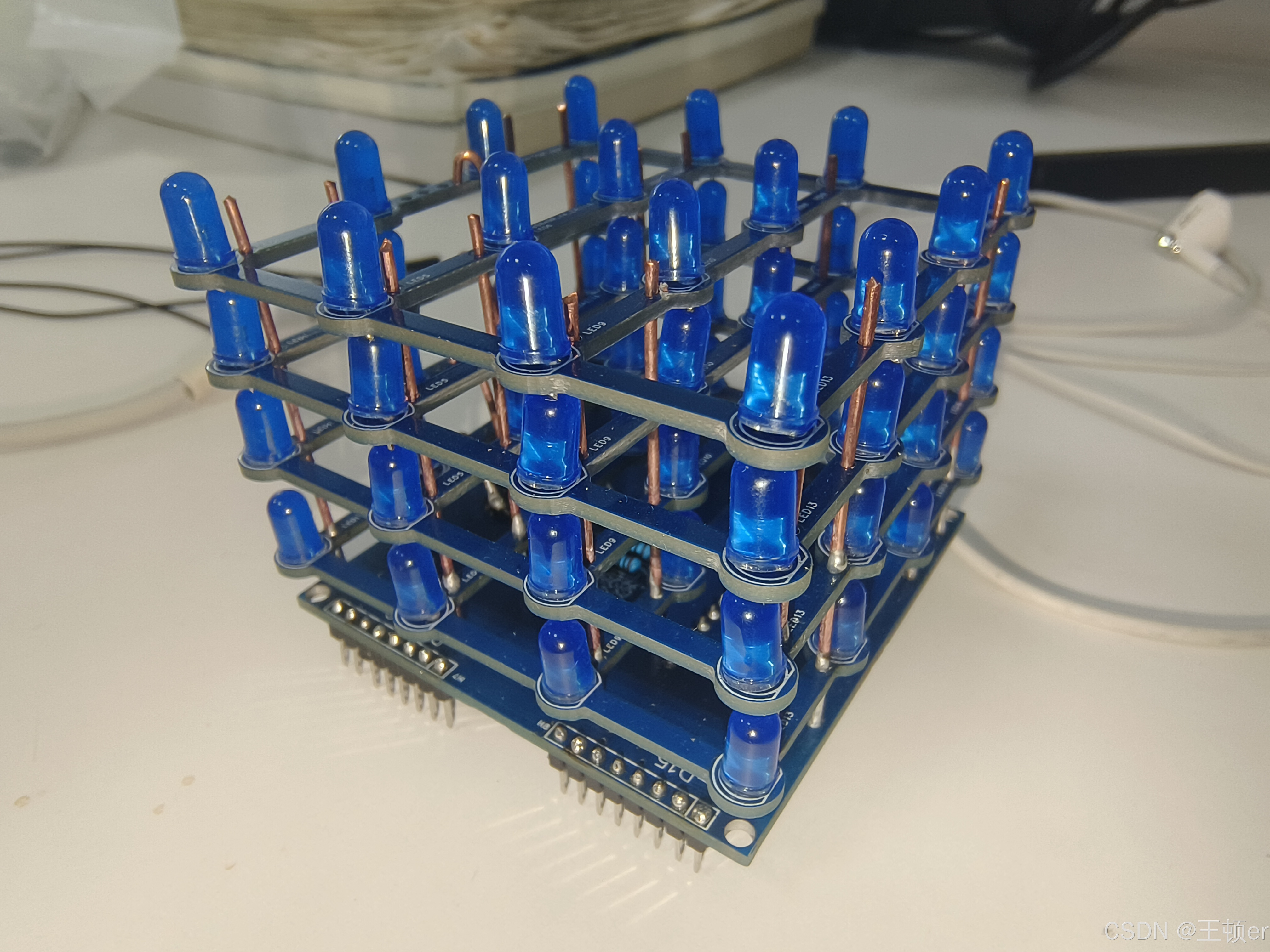
这里附一下开源地址吧:https://github.com/tarantula3/4x4x4-LED-Cube
里面有打板文件只不过使用arduino nano做的插拔设计,并且只有的gerber文件我们还不好在此基础上进行修改,所以为了简单省事做了把所有引脚都引出来的改进,不过就不太美观。
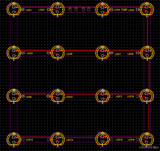
附上原理图和PCB图:
顶层板
(这个要打四个)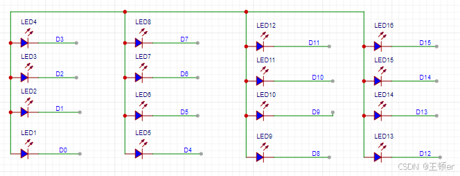
底层板


尺寸: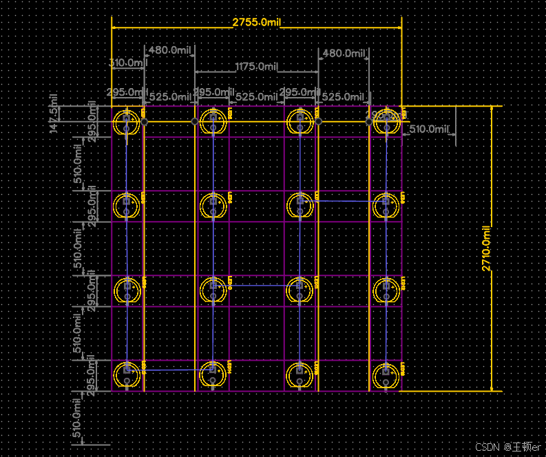

根据esp32s 做插拔设计的板子待续。。。。。

有“AI”的1024 = 2048,欢迎大家加入2048 AI社区
更多推荐
 25
25 0
0- 0


 已为社区贡献2条内容

所有评论(0)