【瑞萨RA MCU创意氛围赛速通】瑞萨RA6M5单片机之UART串口输出DHT11数据
串口通讯 (Serial Communication) 是一种设备间非常常用的串行通讯方式,因为它简单便捷,因此大部分电子设备都支持该通讯方式,电子工程师在调试设备时也经常使用该通讯方式输出调试信息。在计算机科学里,大部分复杂的问题都可以通过分层来简化。如芯片被分为内核层和片上外设。对于通讯协议,我们也以分层的方式来理解,最基本的是把它分为物理层和协议层。物理层规定通讯系统中具有机械、电子功能部分
【瑞萨RA MCU创意氛围赛速通】瑞萨RA6M5单片机之UART串口输出DHT11数据
1.串口通信协议
1.1串口通信协议简介
串口通讯 (Serial Communication) 是一种设备间非常常用的串行通讯方式,因为它简单便捷,因此
大部分电子设备都支持该通讯方式,电子工程师在调试设备时也经常使用该通讯方式输出调试
信息。在计算机科学里,大部分复杂的问题都可以通过分层来简化。如芯片被分为内核层和片上
外设。对于通讯协议,我们也以分层的方式来理解,最基本的是把它分为物理层和协议层。物理
层规定通讯系统中具有机械、电子功能部分的特性,确保原始数据在物理媒体的传输。协议层主
要规定通讯逻辑,统一收发双方的数据打包、解包标准。
2.SCI
2.1SCI简介
SCI(Serial Communications Interface),意为串行通信接口,是相对与并行通信的概念,是串行通
信技术的一种总称。包括了 UART,SPI 等串行通信技术。RA6M5 的 SCI 模块是一个有 10 个通
道的异步/同步串行接口。包含如下功能:
• UART
• 8 位时钟同步接口
• 简易 IIC(只能用作主机)
• 简易 SPI
• 智能卡接口(符合 ISO/IEC 7816-3 国际标准)
• 曼彻斯特接口
• 增强的串行接口
另外,SCI0、SCI3~SCI9 有独立的 FIFO 缓冲区。
2.2SCI 的结构框图
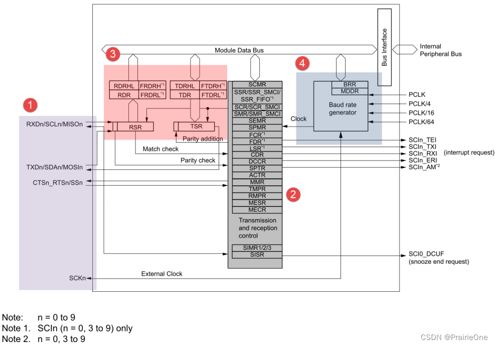
2.3功能引脚
RXDn/SCLn/MISOn:
• RXDn:UART 接收数据输入。
• SCLn:I2C 时钟信号输入或输出。
• MISOn:SPI 主机信号输入,从机信号输出。
TXDn/SDAn/MOSIn:
• TXDn:UART 发送数据输出。
• SDAn:I2C 数据输入或输出。
• MOSIn:SPI 从机信号输入,主机信号输出。
SSn/CTSn_RTSn:
• SSn:片选信号输入,低电平有效。
• CTSn_RTSn:清除以发送(Clear to Send)或请求以发送(Request to Send)。低电平有效。如果使能 RTS 流控制,当 UART 接收器准备好接收新数据时就会将 RTS 变成低电平;当接收寄存器已满时,RTS 将被设置为高电平。如果使能 CTS 流控制,发送器在发送下一帧数据之前会检测 CTS 引脚,如果为低电平,表示可以发送数据,如果为高电平则在发送完当前数据帧之后停止发送,该引脚只适用于硬件流控制。
CTSn (n = 0, 3 to 9):清除以发送 (Clear to Send), 适用于硬件流控制。
SCKn:时钟输出或输入引脚,适用于同步通信。
2.4UART 波特率计算
决定串口波特率的寄存器有 BRR(Bite Rate Rigister),SEMR(Serial Extended Mode Rigister)和
MDDR(Modulation Duty Register)。波特率与寄存器的值的公式如图 19_8 所示。N 表示 BRR 寄
存器的值,B 是波特率,PCLK 是外设时钟的频率(单位:MHz)。BGDM(Baud Rate Generator
Double-Speed Mode Select)在 RA6M5 中,SCI 挂载在 PHBIU(Peripheral High Speed Bus Interface
Unit)总线上,使用时钟 PCLKA,该时钟默认频率为 100MHz。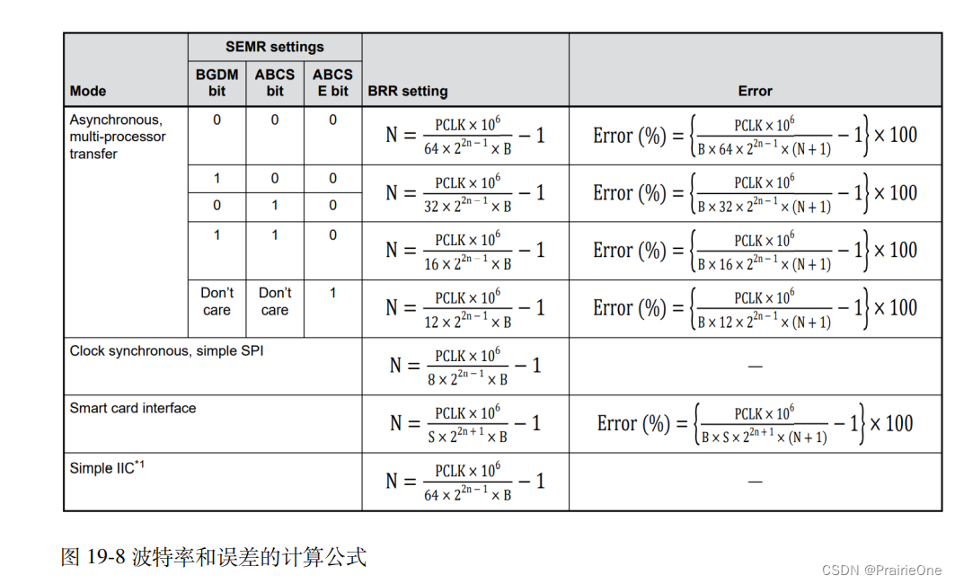
3.硬件设计
为利用 UART 实现开发板与电脑通信,需要用到一个 USB 转串口(UART)的芯片:CH340G。CH340G 是一个 USB 总线的转接芯片,实现 USB 转 UART、USB 转 lrDA 红外或者 USB 转打印机接口,我们使用其 USB 转 UART 功能。具体电路设计见下图。
我们将 CH340G 的 TXD 引脚与 UART4 的 RXD 引脚连接,CH340G 的 RXD 引脚与 UART4 的TXD 引脚连接。CH340G 芯片集成在开发板上,其地线 (GND) 已与控制器的 GND 连通。
即P511接RX,P512接TX.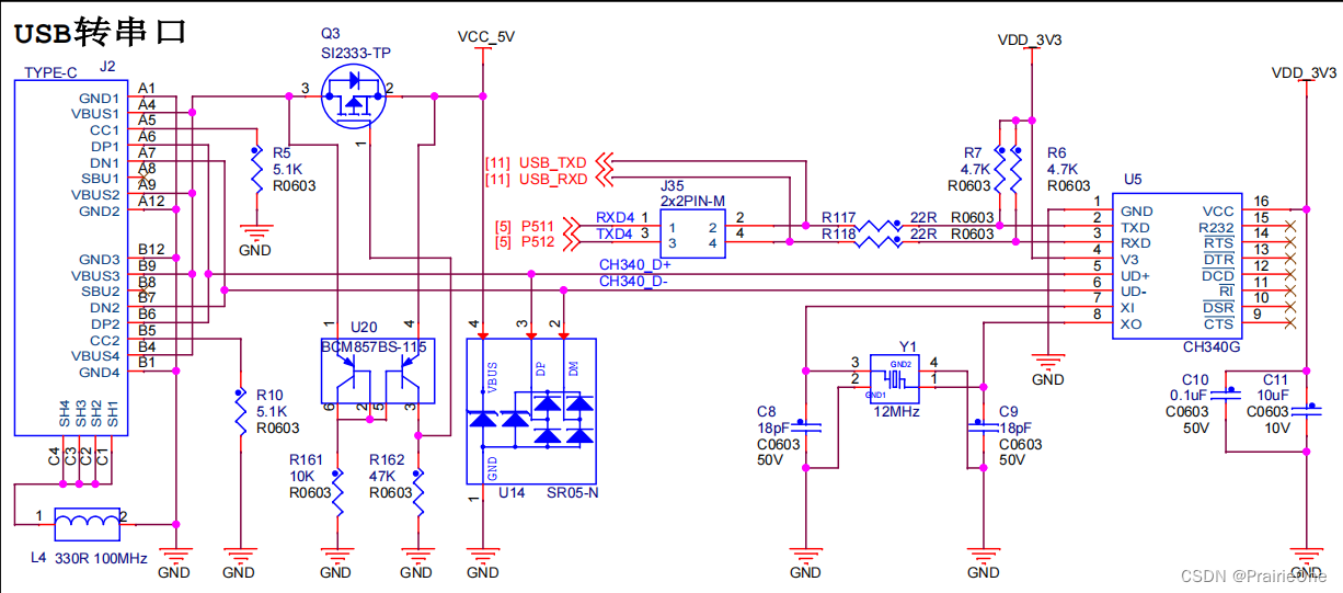
4.效果展示以及代码
效果如图所示: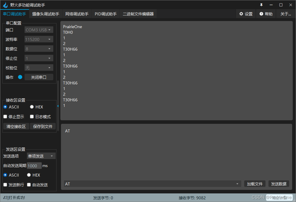
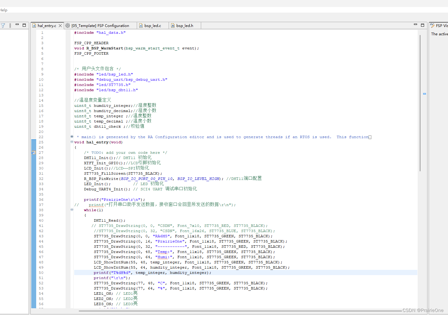
主函数代码:
#include "hal_data.h"
/*
 * 作者:PrairieOne
 * csdn:PrairieOne
 * 邮箱:prairieone1024@163.com
 * 嵌入式技术交流群:738655377
 */
FSP_CPP_HEADER
void R_BSP_WarmStart(bsp_warm_start_event_t event);
FSP_CPP_FOOTER


/* 用户头文件包含 */
#include "led/bsp_led.h"
#include "debug_uart/bsp_debug_uart.h"
#include "led/ST7735.h"
#include "led/bsp_dht11.h"

//温湿度变量定义
uint8_t humdity_integer;//湿度整数
uint8_t humdity_decimal;//湿度小数
uint8_t temp_integer ;//温度整数
uint8_t temp_decimal ;//温度小数
uint8_t dht11_check ;//校验值

/*******************************************************************************************************************//**
 * main() is generated by the RA Configuration editor and is used to generate threads if an RTOS is used.  This function
 * is called by main() when no RTOS is used.
 **********************************************************************************************************************/
void hal_entry(void)
{
    /* TODO: add your own code here */
    DHT11_Init();// DHT11 初始化
    XTFT_Init_GPIO();//LCD引脚初始化
    LCD_Init();//LCD——SPI初始化
    ST7735_FillScreen(ST7735_BLACK);
    R_BSP_PinWrite(BSP_IO_PORT_00_PIN_10, BSP_IO_LEVEL_HIGH); //DHT11端口配置
    LED_Init();         // LED 初始化
    Debug_UART4_Init(); // SCI4 UART 调试串口初始化

    printf("PrairieOne\r\n");
//    printf("打开串口助手发送数据,接收窗口会回显所发送的数据\r\n");
    while(1)
    {
        DHT11_Read();
       // ST7735_DrawString(0, 0, "CSDN", Font_7x10, ST7735_RED, ST7735_BLACK);
        //ST7735_DrawString(0, 32, "CSDN", Font_16x26, ST7735_BLUE, ST7735_BLACK);
        ST7735_DrawString(0, 0, "RA6M5", Font_11x18, ST7735_GREEN, ST7735_BLACK);
        ST7735_DrawString(0, 16, "PrairieOne", Font_11x18, ST7735_GREEN, ST7735_BLACK);
        ST7735_DrawString(0, 32, "-----------", Font_11x18, ST7735_RED, ST7735_BLACK);
        ST7735_DrawString(0, 48, "Temp:", Font_11x18, ST7735_GREEN, ST7735_BLACK);
        ST7735_DrawString(0, 64, "Humi:", Font_11x18, ST7735_GREEN, ST7735_BLACK);
        LCD_ShowIntNum(55, 48, temp_integer, Font_11x18, ST7735_GREEN, ST7735_BLACK);
        LCD_ShowIntNum(55, 64, humdity_integer, Font_11x18, ST7735_GREEN, ST7735_BLACK);
        printf("T%dH%d", temp_integer, humdity_integer);
        printf("\r\n");
        ST7735_DrawString(77, 48, "C", Font_11x18, ST7735_GREEN, ST7735_BLACK);
        ST7735_DrawString(77, 64, "%", Font_11x18, ST7735_GREEN, ST7735_BLACK);
        LED1_ON; // LED1亮
        LED2_ON; // LED2亮
        LED3_ON; // LED3亮
        printf("1\r\n");
        R_BSP_SoftwareDelay(1, BSP_DELAY_UNITS_SECONDS); //延时1秒
        LED1_OFF; // LED1灭
        LED2_OFF; // LED2灭
        LED3_OFF; // LED3灭
        printf("2\r\n");
//        printf((uint8_t *)123);
        R_BSP_SoftwareDelay(1, BSP_DELAY_UNITS_SECONDS); //延时1秒
    }


#if BSP_TZ_SECURE_BUILD
    /* Enter non-secure code */
    R_BSP_NonSecureEnter();
#endif
}

/*******************************************************************************************************************//**
 * This function is called at various points during the startup process.  This implementation uses the event that is
 * called right before main() to set up the pins.
 *
 * @param[in]  event    Where at in the start up process the code is currently at
 **********************************************************************************************************************/
void R_BSP_WarmStart(bsp_warm_start_event_t event)
{
    if (BSP_WARM_START_RESET == event)
    {
#if BSP_FEATURE_FLASH_LP_VERSION != 0

        /* Enable reading from data flash. */
        R_FACI_LP->DFLCTL = 1U;

        /* Would normally have to wait tDSTOP(6us) for data flash recovery. Placing the enable here, before clock and
         * C runtime initialization, should negate the need for a delay since the initialization will typically take more than 6us. */
#endif
    }

    if (BSP_WARM_START_POST_C == event)
    {
        /* C runtime environment and system clocks are setup. */

        /* Configure pins. */
        R_IOPORT_Open (&g_ioport_ctrl, g_ioport.p_cfg);
    }
}

#if BSP_TZ_SECURE_BUILD

BSP_CMSE_NONSECURE_ENTRY void template_nonsecure_callable ();

/* Trustzone Secure Projects require at least one nonsecure callable function in order to build (Remove this if it is not required to build). */
BSP_CMSE_NONSECURE_ENTRY void template_nonsecure_callable ()
{

}
#endif
bsp_debug_uart.c代码:
#include "bsp_debug_uart.h"


/* 调试串口 UART4 初始化 */
void Debug_UART4_Init(void)
{
    fsp_err_t err = FSP_SUCCESS;

    err = R_SCI_UART_Open (&g_uart4_ctrl, &g_uart4_cfg);
    assert(FSP_SUCCESS == err);
}


/* 发送完成标志 */
volatile bool uart_send_complete_flag = false;


/* 串口中断回调 */
void debug_uart4_callback (uart_callback_args_t * p_args)
{
    switch (p_args->event)
    {
        case UART_EVENT_RX_CHAR:
        {
            /* 把串口接收到的数据发送回去 */
            R_SCI_UART_Write(&g_uart4_ctrl, (uint8_t *)&(p_args->data), 1);
            break;
        }
        case UART_EVENT_TX_COMPLETE:
        {
            uart_send_complete_flag = true;
            break;
        }
        default:
            break;
    }
}


/* 重定向 printf 输出 */
#if defined __GNUC__ && !defined __clang__
int _write(int fd, char *pBuffer, int size); //防止编译警告
int _write(int fd, char *pBuffer, int size)
{
    (void)fd;
    R_SCI_UART_Write(&g_uart4_ctrl, (uint8_t *)pBuffer, (uint32_t)size);
    while(uart_send_complete_flag == false);
    uart_send_complete_flag = false;

    return size;
}
#else
int fputc(int ch, FILE *f)
{
    (void)f;
    R_SCI_UART_Write(&g_uart4_ctrl, (uint8_t *)&ch, 1);
    while(uart_send_complete_flag == false);
    uart_send_complete_flag = false;

    return ch;
}
#endif
bsp_debug_uart.h代码:
#ifndef __BSP_DEBUG_UART_H
#define	__BSP_DEBUG_UART_H
#include "hal_data.h"
#include "stdio.h"


void Debug_UART4_Init(void);


#endif
5.配置参数
串口配置如下图所示,需要主要,引脚一定是P511\P512,引脚选错是无法监测到输出的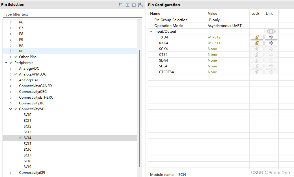
在“属性”窗口中配置名字(name)、通道(Channel)、
回调函数(Callback)名字即可,引脚(Pins)、波特率(Baud Rate)等其他的属性按照默认的配
置即可。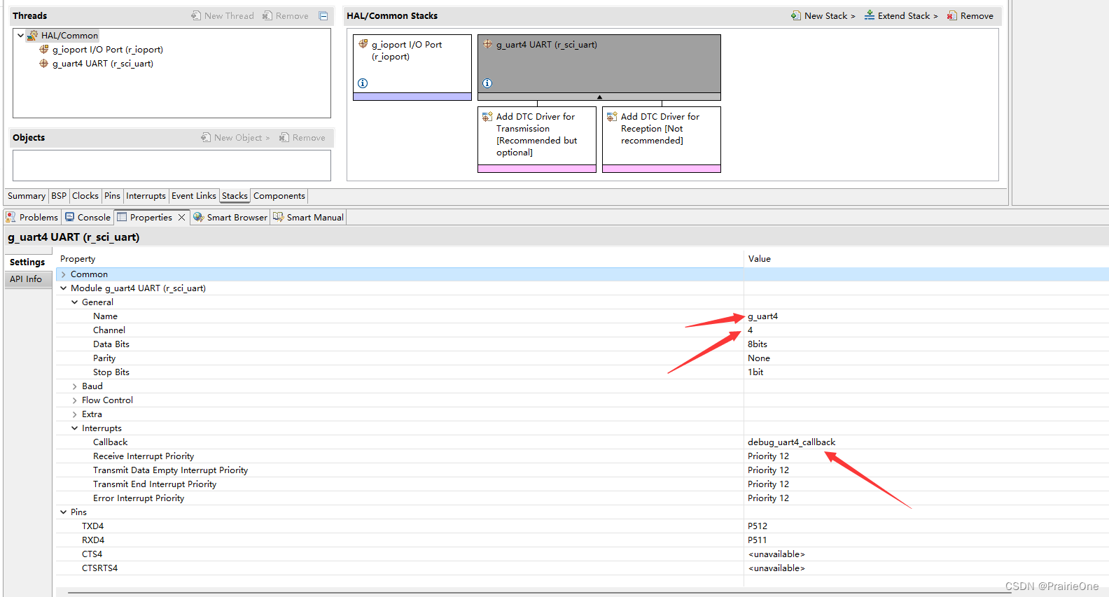
Name:名字,根据读者需求设置即可。
Channel :通道,根据 SCI 号设置即可,例如实验使用 SCI4,则这里配置为通道 4。
Data Bits: 每个字(word)的比特(bit)数,默认为 8bits
Parity :校验模式,可选择“Odd”奇校验,“Even”偶校验或“None”无校验。
Stop Bits: 停止位,可选 1 或 2bit。
Baud Rate :波特率
Baud Rate Modulation :波特率调制,通过调整时钟周期,以减少申请波特率与实际波特率之间的误差。
Max Error(%) :计算波特率时允许的最大百分比误差。
Callback: 回调函数的名字,根据读者需求设置即可。
Receive Interrupt Priority :接收中断优先级
Transmit Data Empty InterruptPriority:发送数据空中断优先级
Transmit End Interrupt Priority: 发送完成中断优先级
Error Interrupt Priority: 错误中断优先级
使用 printf 函数时,需要使用到堆,默认情况下堆的大小为 0,因此我们需要修改堆的大小。可
以在 FSP 配置界面中的“BSP”属性栏的“RA Common”中通过修改“Heap size”来设置堆区大
小。这里需要设置为 8 的整数倍,推荐至少为 4K(0x1000)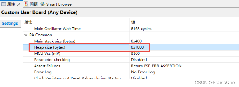
遇事不决,可问春风!

有“AI”的1024 = 2048,欢迎大家加入2048 AI社区
更多推荐
 1
1 0
0- 0


 已为社区贡献8条内容

所有评论(0)